Jeep Grand Cherokee WJ. Manual - part 81
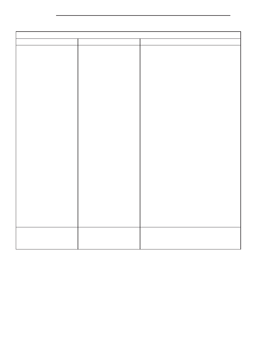
Battery Diagnosis
Condition
Possible Causes
Correction
The battery state-of-charge
cannot be maintained.
1. The battery has an
incorrect size or rating for
this vehicle.
2. The battery terminal
connections are loose or
corroded.
3. The generator drive belt is
slipping.
4. The electrical system
ignition-off draw is excessive.
5. The battery is faulty.
6. The starting system is
faulty.
7. The charging system is
faulty.
8. Electrical loads exceed the
output of the charging
system.
9. Slow driving or prolonged
idling with high-amperage
draw systems in use.
1. Refer to Battery in the index of this service
manual for the location of the proper battery
specifications. Replace an incorrect battery, as
required.
2. Refer to Voltage Drop Test in this section for
the proper test procedures. Clean and tighten the
battery terminal connections, as required.
3. Refer to Accessory Drive Belt Diagnosis in the
index of this service manual for the location of the
proper accessory drive belt diagnosis and testing
procedures. Replace or adjust the faulty
generator drive belt, as required.
4. Refer to Ignition-Off Draw Test in this section
for the proper test procedures. Repair the faulty
electrical system, as required.
5. Determine the battery cranking capacity. Refer
to Load Test in this section for the proper test
procedures. Replace the faulty battery, as
required.
6. Determine if the starting system is performing
to specifications. Refer to Starting System in the
index of this service manual for the location of the
proper starting system diagnosis and testing
procedures. Repair the faulty starting system, as
required.
7. Determine if the charging system is performing
to specifications. Refer to Charging System in the
index of this service manual for the location of the
proper charging system diagnosis and testing
procedures. Repair the faulty charging system, as
required.
8. Inspect the vehicle for aftermarket electrical
equipment which might cause excessive electrical
loads.
9. Advise the vehicle operator, as required.
The battery will not accept a
charge.
1. The battery is faulty.
1. Refer to Battery Charging in the index of this
service manual for the location of the proper
battery charging procedures. Charge or replace
the faulty battery, as required.
ABNORMAL BATTERY DISCHARGING
Any of the following conditions can result in abnor-
mal battery discharging:
1. Corroded or loose battery posts and terminal
clamps.
2. A loose or worn generator drive belt.
3. Electrical loads that exceed the output of the
charging system. This can be due to equipment installed
after manufacture, or repeated short trip use.
4. Slow driving speeds (heavy traffic conditions) or
prolonged idling, with high-amperage draw systems
in use.
5. A faulty circuit or component causing excessive
ignition-off draw.
6. A faulty or incorrect charging system compo-
nent. Refer to Charging System in the index of this
service manual for the location of the proper charg-
ing system diagnosis and testing procedures.
7. A faulty or incorrect starting system component.
Refer to Starting System in the index of this ser-
vice manual for the location of the proper starting
system diagnosis and testing procedures.
8. A faulty or incorrect battery.
8A - 8
BATTERY
WJ
DIAGNOSIS AND TESTING (Continued)