Jeep Grand Cherokee WJ. Manual - part 76


  Index      Jeep     Jeep Grand Cherokee WJ - service repair manual 2001 year


Search            


Content   ..  74  75  76  77   ..


Jeep Grand Cherokee WJ. Manual - part 76


(8) After engine has reached normal operating

temperature, shut engine off and allow it to cool.

(9) Remove coolant tank cap.
(10) Add coolant into the coolant tank up to the

COLD mark. If possible, only add coolant when
the engine is cold. Coolant level in a warm
engine will be higher in the tank due to ther-
mal expansion.

(11) After the engine has been operated through a

few heat-up and cool-down cycles, recheck the coolant
level in the tank.

COOLANT REPLACEMENT

It is recommended that the cooling system be

drained and flushed at 84,000 kilometers (52,500
miles), or 3 years, whichever occurs first. Then every
two years, or 48,000 kilometers (30,000 miles),
whichever occurs first.

REMOVAL AND INSTALLATION

COOLING MODULE ASSEMBLY

The cooling module assembly includes the radiator,

charge air cooler (intercooler) and the A/C condenser.
To replace any one of these components, the entire
assembly must be removed from the vehicle and then
disassembled.

WARNING: CONSTANT TENSION HOSE CLAMPS
ARE USED ON MOST COOLING SYSTEM HOSES.
WHEN REMOVING OR INSTALLING, USE ONLY
TOOLS DESIGNED FOR SERVICING THIS TYPE OF
CLAMP

(Fig.

15).

ALWAYS

WEAR

SAFETY

GLASSES WHEN SERVICING CONSTANT TENSION
CLAMPS.

CAUTION: A number or letter is stamped into the
tongue of constant tension clamps (Fig. 16). If
replacement is necessary, use only an original
equipment clamp with matching number or letter.

REMOVAL

WARNING: DO

NOT

REMOVE

THE

CYLINDER

BLOCK DRAIN-PLUG, THE COOLANT TANK CAP,
THE RADIATOR FILL VENT VALVE, OR LOOSEN
THE RADIATOR DRAINCOCK WITH THE SYSTEM
HOT AND PRESSURIZED. SERIOUS BURNS FROM
THE COOLANT CAN OCCUR.

CAUTION: Before removing the cooling module
assembly, note the location of each of the air seals.
These seals are used to direct air through the con-
denser, radiator and charge air cooler. The air seals

must be reinstalled in their proper locations in
order for the air conditioning and engine cooling
systems to perform as designed.

(1) Disconnect the negative battery cable.
(2) Raise the vehicle on the hoist.
(3) Remove the lower front splash shield
(4) Drain the cooling system. Refer to Group 7,

Cooling System for the procedure.

(5) Remove the lower radiator hose from the radi-

ator (Fig. 17).

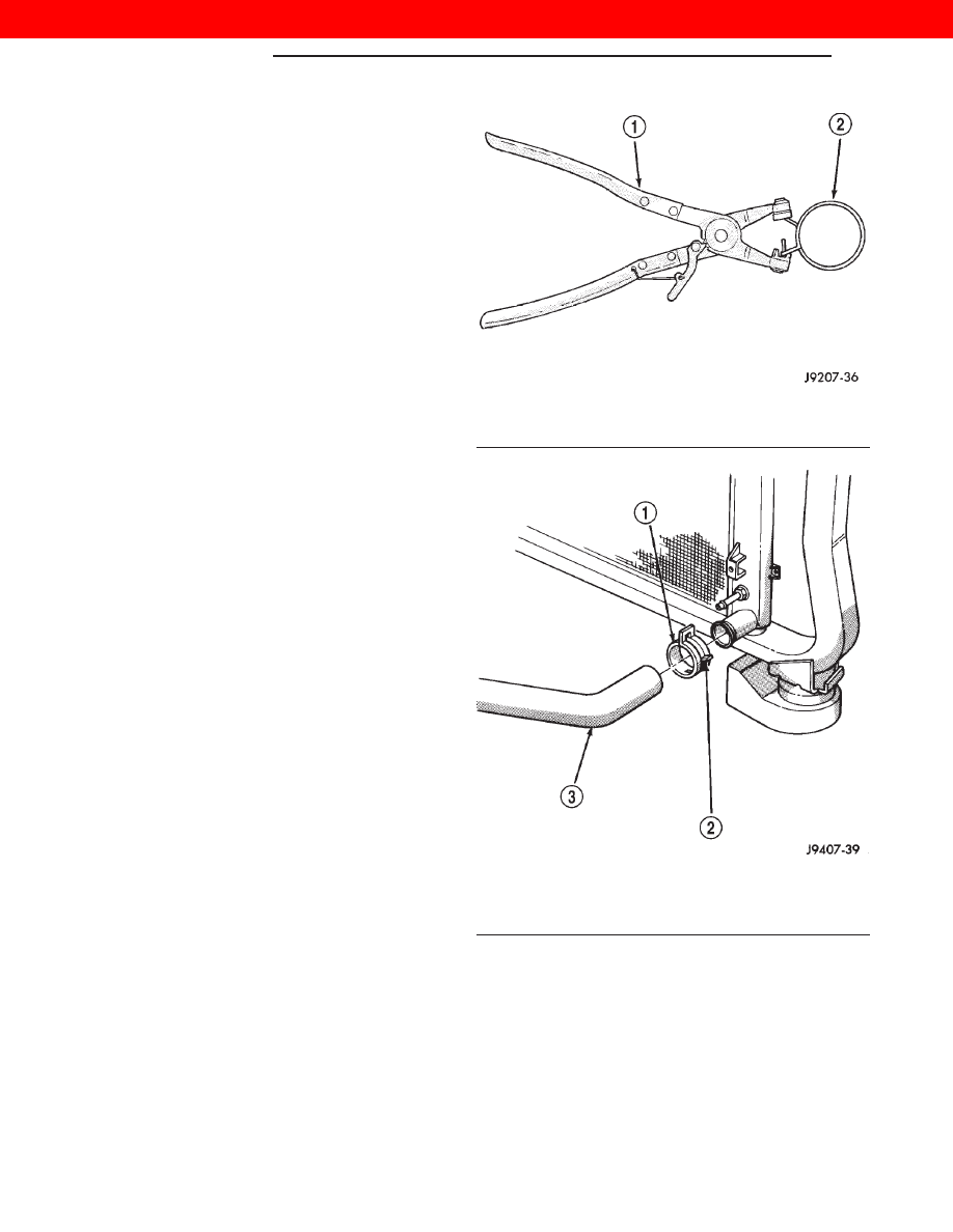
Fig. 15 Hose Clamp Tool

1 – HOSE CLAMP TOOL 6094
2 – HOSE CLAMP

Fig. 16 Clamp Number/Letter Location

1 – TYPICAL CONSTANT TENSION HOSE CLAMP
2 – CLAMP NUMBER/LETTER LOCATION
3 – TYPICAL HOSE

7 - 20

COOLING SYSTEM

WJ

SERVICE PROCEDURES (Continued)

2000 JEEP GRAND CHEROKEE

(6) Remove the (2) lower fan shroud retaining

bolts (Fig. 17).

(7) Remove the transmission fluid cooler lines from

the radiator (Fig. 17).

(8) Lower the vehicle from the hoist.
(9) Remove the intercooler inlet and outlet hoses

from the intercooler (Fig. 18).

(10) Remove the right and left headlamp assem-

blies from the vehicle. Refer to Group 8L, Lamps for
the procedure.

(11) Remove the front fascia. Refer to Group 13,

Frame and Bumpers for the procedure.

(12) Disconnect the ambient temperature sensor

and unclip the wire harness from the headlamp mod-
ule mounting (HMM) assembly.

(13) Disconnect the right and left headlamp mod-

ule wire harnesses at the 10-way connectors. Located
just above the front bumper to the right and left of
the A/C condenser.

(14) Remove

the

headlamp

module

mounting

(HMM) assembly. Refer to Group 23, Body for the
procedure.

NOTE: Mark the position of the hood latch in rela-
tion to its mounting bracket. This will aid in aligning
the hood latch during reassembly.

(15) Remove the hood latch retaining fasteners

and position it out of the way.

(16) Remove the hood latch support brackets from

the vehicle.

(17) Remove the upper fan shroud retaining bolts.
(18) Remove the radiator closure pane from the

vehicle. Refer to Group 23, Body for the procedure.

(19) Remove the viscous cooling fan and carefully

set inside of the fan shroud.

(20) Remove the radiator overflow hose from the

radiator and position out of the way.

(21) Remove the upper radiator hose from the

radiator.

(22) Disconnect the electric radiator cooling fan

electrical connector. Located under the intercooler
outlet hose.

(23) If equipped, recover the refrigerant. Refer to

Group 24, Heating and Air Conditioning for the pro-
cedure.

(24) Remove the intake air duct from the vehicle

(Fig. 19).

(25) Remove the power steering cooler retaining

bolts (Fig. 19) and position the cooler aside.

(26) Remove the suction and discharge lines from

the A/C condenser assembly (Fig. 19).

(27) Remove the fan shroud and both cooling fans

as an assembly from the vehicle.

(28) Remove the cooling module assembly retain-

ing bolts and remove the radiator, intercooler and
A/C condenser from the vehicle.

Fig. 17 Transmission Fluid Cooler Lines At Radiator

1 – TRANSMISSION FLUID COOLER LINES
2 – FAN SHROUD
3 – LOWER RADIATOR HOSE
4 – FRONT SPLASH SHIELD
5 – LOWER FAN SHROUD RETAINING BOLTS

Fig. 18 Intercooler Hoses

1 – INTERCOOLER INLET HOSE
2 – COOLANT RECOVERY HOSE
3 – REFRIGERANT LINE SUPPORT BRACKET
4 – INTERCOOLER OUTLET HOSE
5 – FAN SHROUD

WJ

COOLING SYSTEM

7 - 21

REMOVAL AND INSTALLATION (Continued)

2000 JEEP GRAND CHEROKEE

CAUTION: Care must be taken not to damage the
cooling core fins of the radiator and A/C condenser
during removal, service and installation of the cool-
ing module assembly. Reduced cooling capability
will result.

(29) Place the assembly in a upright position on

the bench or floor.

(30) Disassemble the cooling module by removing

the retaining bolts for the component that requires
replacement or inspection.

INSTALLATION

CAUTION: The bottom of the radiator is equipped
with two alignment dowels that fit into holes in the
lower radiator support panel. Rubber biscuits (insu-
lators) are installed on these dowels. Be certain
these biscuits are installed and in good condition
prior to installing the cooling module assembly.

(1) Assemble

the

cooling

module.

Torque

the

retaining bolts to 30 N·m (22 ft. lbs.).

(2) Position the cooling module assembly and

install the retaining bolts (Fig. 20). Torque the bolts
to 41 N·m (30 ft. lbs.).

(3) Install the fan shroud, electric and viscous cool-

ing fans as an assembly in the vehicle. Refer to
Group 7, Cooling System - Cooling System Fan for
the procedure.

(4) Install the suction and discharge refrigerant

lines on the A/C condenser assembly (Fig. 20). Torque
the retaining nuts to 28 N·m (21 ft. lbs.). Be certain
the sealing gaskets are free of tears and well lubri-
cated with R-134a Pag Oil.

(5) Position the power steering cooler and install

the retaining bolts (Fig. 20).

(6) Charge the refrigerant system. Refer to Group

24, Heating and Air Conditioning for the procedure.

(7) Connect the electric radiator cooling fan electri-

cal connector.

(8) Install the intake air duct on the vehicle (Fig.

20).

(9) Install the upper radiator hose on the radiator.
(10) Install the radiator overflow hose on the radi-

ator

Fig. 19 Cooling Module Assembly

1 – INTAKE AIR DUCT
2 – RADIATOR
3 – COOLING SYSTEM VENT
4 – POWER STEERING FLUID COOLER
5 – POWER STEERING COOLER RETAINING BOLTS
6 – A/C CONDENSER
7 – REFRIGERANT LINE RETAINING NUTS
8 – 10–WAY HEADLAMP MODULE CONNECTOR
9 – INTERCOOLER
10 – A/C CONDENSER RETAINING BOLTS

Fig. 20 Cooling Module Assembly

1 – INTAKE AIR DUCT
2 – RADIATOR
3 – COOLING SYSTEM VENT
4 – POWER STEERING FLUID COOLER
5 – POWER STEERING COOLER RETAINING BOLTS
6 – A/C CONDENSER
7 – REFRIGERANT LINE RETAINING NUTS
8 – 10–WAY HEADLAMP MODULE CONNECTOR
9 – INTERCOOLER
10 – A/C CONDENSER RETAINING BOLTS

7 - 22

COOLING SYSTEM

WJ

REMOVAL AND INSTALLATION (Continued)

2000 JEEP GRAND CHEROKEE

(11) Install the intercooler inlet and outlet hoses

on the intercooler (Fig. 21).

(12) Install the radiator closure panel on the vehi-

cle. Refer to Group 23, Body for the procedure.

(13) Install the upper fan shroud retaining bolts.

Torque the bolts to 15 N·m (132 in. lbs.).

(14) Install the hood latch support brackets and

the hood latch on the vehicle.

(15) Install

the

headlamp

module

mounting

(HMM) assembly. Refer to Group 23, Body for the
procedure.

(16) Connect the right and left headlamp module

wire harnesses at the 10-way connectors. Located
just above the front bumper to the right and left of
the a/c condenser.

(17) Connect the ambient temperature sensor and

clip the wire harness on the headlamp module
mounting assembly.

(18) Install the front fascia. Refer to Group 13,

Frame and Bumpers for the procedure.

(19) Install the right and left headlamp assemblies

on the vehicle. Refer to Group 8L, Lamps for the pro-
cedure.

(20) Raise the vehicle on the hoist.
(21) Install the (2) lower fan shroud retaining

bolts. Torque bolts to 12 N·m (105in. lbs.).

(22) Install the lower radiator hose on the radiator.

(23) Install the transmission fluid cooler lines on

the radiator (Fig. 22).

(24) Install the lower front splash shield
(25) Lower the vehicle on the hoist.
(26) Fill the cooling system. Refer to Group 7,

Cooling System for the procedure.

(27) Connect the negative battery cable.

RADIATOR

The cooling module assembly includes the radiator,

charge air cooler (intercooler) and the A/C condenser.
To replace any one of these components, the entire
assembly must be removed from the vehicle and then
disassembled. Refer to the Cooling Module removal
and installation procedure for replacement of the
radiator.

FAN BLADE REMOVAL

FAN BLADE REMOVAL

Accessory drive belt removal is not necessary for

fan blade or viscous fan drive removal.

(1) Disconnect negative battery cable from battery.
(2) The thermal viscous fan drive/fan blade assem-

bly is attached (threaded) to the fan pulley shaft
(Fig. 23). Remove fan blade/viscous fan drive assem-
bly from fan pulley by turning mounting nut counter-
clockwise as viewed from front. Threads on viscous
fan drive are RIGHT HAND. Snap-On

t 36 MM Fan

Wrenches (number SP346) can be used to turn the
mounting nut and to hold the fan pulley from rotat-
ing.

Fig. 21 Intercooler Hoses

1 – INTERCOOLER INLET HOSE
2 – COOLANT RECOVERY HOSE
3 – REFRIGERANT LINE SUPPORT BRACKET
4 – INTERCOOLER OUTLET HOSE
5 – FAN SHROUD

Fig. 22 Transmission Fluid Cooler Lines At Radiator

1 – TRANSMISSION FLUID COOLER LINES
2 – FAN SHROUD
3 – LOWER RADIATOR HOSE
4 – FRONT SPLASH SHIELD
5 – LOWER FAN SHROUD RETAINING BOLTS

WJ

COOLING SYSTEM

7 - 23

REMOVAL AND INSTALLATION (Continued)

2000 JEEP GRAND CHEROKEE


Content   ..  74  75  76  77   ..