Jeep Grand Cherokee WJ. Manual - part 70


  Index      Jeep     Jeep Grand Cherokee WJ - service repair manual 2001 year


Search            


Content   ..  68  69  70  71   ..


Jeep Grand Cherokee WJ. Manual - part 70


WARNING: BECAUSE OF HIGH SPRING TENSION,
DO NOT ATTEMPT TO DISASSEMBLE AUTOMATIC
TENSIONER. UNIT IS SERVICED AS AN ASSEMBLY
(EXCEPT FOR PULLEY ON 4.7L TENSIONER).

(3) Remove pulley bolt. Remove pulley from ten-

sioner (4.7L ONLY).

INSTALLATION

(1) Install pulley and pulley bolt to tensioner.

Tighten bolt to 61 N·m (45 ft. lbs.) torque (4.7L
engine only).

(2) Install

tensioner

assembly

to

mounting

bracket. (4.0L engine) align the two dowels on the
tensioner with the mounting bracket and hand start
the bolt. Tighten bolt to 28 N·m (250 in. lbs.). (4.7L
engines) An indexing slot is located on back of ten-
sioner. Align this slot to the head of the bolt on the
front cover. Install the mounting bolt. Tighten bolt to
41 N·m (30 ft. lbs.).

CAUTION: To prevent damage to coil case, coil
mounting bolts must be torqued.

(3) Install drive belt. Refer to Belt Removal/Instal-

lation in this group.

(4) Check belt indexing marks.

COOLING SYSTEM FAN 4.0L AND 4.7L
ENGINES

VISCOUS FAN

REMOVAL

(1) Disconnect negative battery cable from battery.

NOTE: The 4.0L engine does not require special
tool 6958 spanner wrench or adapters 8346 to
remove the fan drive.

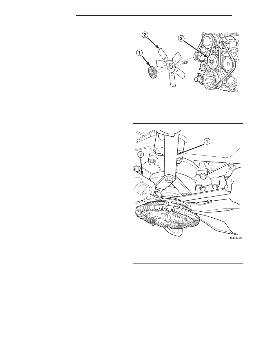
(2) The thermal viscous fan drive/fan blade assem-

bly is attached (threaded) to water pump hub shaft
(Fig. 61). Remove fan blade/viscous fan drive assem-
bly from water pump by turning mounting nut coun-
terclockwise as viewed from front. Threads on
viscous fan drive are RIGHT HAND. Using spanner
wrench 6958 with adapter pins 8346 (4.7L engine
only) and a suitable fan wrench loosen the fan drive.
(Fig. 62)

(3) Do not attempt to remove fan/viscous fan drive

assembly from vehicle at this time.

(4) Do not unbolt fan blade assembly from viscous

fan drive at this time.

(5) Remove fan shroud-to-upper crossmember nuts.
(6) Remove fan shroud and fan blade/viscous fan

drive assembly as a complete unit from vehicle.

(7) After removing fan blade/viscous fan drive

assembly, do not place viscous fan drive in horizon-
tal position. If stored horizontally, silicone fluid in
the viscous fan drive could drain into its bearing
assembly and contaminate lubricant.

CAUTION: Do not remove water pump pulley-to-wa-
ter pump bolts. This pulley is under belt tension.

(8) Remove four bolts securing fan blade assembly

to viscous fan drive.

Fig. 61 Fan Blade/Viscous Fan Drive—4.7L V-8

Engines

1 – VISCOUS FAN DRIVE
2 – FAN BLADE
3 – WATER PUMP PULLEY

Fig. 62 Fan Blade and Drive—Removal

1 – SPECIAL TOOL 6958 SPANNER WRENCH WITH ADAPTER

PINS 8346

2 – FAN

7 - 42

COOLING SYSTEM

WJ

REMOVAL AND INSTALLATION (Continued)

INSTALLATION

(1) Install fan blade assembly to viscous fan drive.

Tighten bolts to 23 N·m (17 ft. lbs.) torque.

(2) Position fan shroud and fan blade/viscous fan

drive assembly to vehicle as a complete unit.

(3) Position fan shroud to radiator. Be sure the

alignment tabs at the lower part of shroud are placed
into the slots near lower part of radiator. Install and
tighten the two fan shroud-to-upper crossmember
mounting nuts.

Be sure of at least 25 mm (1.0 inches) between tips

of fan blades and fan shroud.

(4) Install fan blade/viscous fan drive assembly to

water pump shaft (Fig. 62).

(5) Connect negative battery cable.

ELECTRIC FAN

The electric fan is only serviced as an assembly.

VISCOUS FAN DRIVE

REMOVAL/INSTALLATION

Refer to Cooling System Fan removal and installa-

tion procedures of the viscous fan drive unit proce-
dures.

Viscous Fan Drive Fluid Pump Out Requirement:

After installing a NEW viscous fan drive, bring the

engine speed up to approximately 2000 rpm and hold
for approximately two minutes. This will ensure
proper fluid distribution within the drive.

CLEANING AND INSPECTION

RADIATOR PRESSURE CAP

CLEANING

Clean the radiator pressure cap using a mild soap

and water only.

INSPECTION

Visually inspect the pressure valve gasket on the

cap. Replace cap if the gasket is swollen, torn or
worn. Inspect the area around radiator filler neck for
white deposits that indicate a leaking cap.

RADIATOR

CLEANING

Clean radiator fins With the engine cold, apply cold

water and compressed air to the back (engine side) of
the radiator to flush the radiator and/or A/C con-
denser of debris.

INSPECTION

The radiator cooling fins should be checked for

damage or deterioration. Inspect cooling fins to make
sure they are not bent or crushed, these areas result
in reduced heat exchange causing the cooling system
to operate at higher temperatures. Inspect the plastic
end tanks for cracks, damage or leaks.

Inspect the radiator neck for damage or distortion.

WATER PUMP

CLEANING

Clean the gasket mating surface. Use caution not

to damage the gasket sealing surface.

INSPECTION

Inspect the water pump assembly for cracks in the

housing, Water leaks from shaft seal, Loose or rough
turning bearing or Impeller rubbing either the pump
body or timing chain case/cover.

FAN BLADE

CLEANING

Clean the fan blades using a mild soap and water.

Do not use an abrasive to clean the blades.

INSPECTION

WARNING: DO

NOT

ATTEMPT

TO

BEND

OR

STRAIGHTEN FAN BLADES IF FAN IS NOT WITHIN
SPECIFICATIONS.

CAUTION: If

fan

blade

assembly

is

replaced

because of mechanical damage, water pump and
viscous fan drive should also be inspected. These
components could have been damaged due to
excessive vibration.

(1) Remove fan blade assembly from viscous fan

drive unit (four bolts).

(2) Lay fan on a flat surface with leading edge fac-

ing down. With tip of blade touching flat surface,
replace fan if clearance between opposite blade and
surface is greater than 2.0 mm (.090 inch). Rocking
motion of opposite blades should not exceed 2.0 mm
(.090 inch). Test all blades in this manner.

(3) Inspect fan assembly for cracks, bends, loose

rivets or broken welds. Replace fan if any damage is
found.

WJ

COOLING SYSTEM

7 - 43

REMOVAL AND INSTALLATION (Continued)

COOLING SYSTEM HOSES

INSPECTION

Inspect the hoses at regular intervals. Replace

hoses that are cracked, feel brittle when squeezed or
swell excessively when the system is pressurized.
The use of molded replacement hoses is recom-
mended. When performing a hose inspection, inspect
the radiator lower hose for proper position and con-
dition of the spring.

SPECIFICATIONS

INFORMATION

The following specifications are published from the

latest information available at the time of publica-
tion. If anything differs between the specifica-
tions found on the Vehicle Emission Control
Information (VECI) label and the following
specifications, use specifications on VECI label.
The VECI label is located in the engine compart-
ment. Refer to Group 25, Emission System for more
information on the VECI label.

COOLING SYSTEM CAPACITIES

DRIVE BELT TENSION

4.0L (6 Cyl. eng.) 4.7L (V-8 eng.)

• Do not attempt to check belt tension with a ten-

sion gauge. System is equipped with an automatic
tensioner. Refer to Automatic Belt Tensioner in
Group 7, Cooling System.

TORQUE SPECIFICATIONS

DESCRIPTION

N·m

Ft.

In.

Lbs.

Lbs.

Automatic Belt Tensioner to
Mounting

Bracket—Bolt

4.0L

28

250

4.7L

41

30

Automatic Belt Tensioner Pulley—

Bolt

(4.7L)

61

45

Block Heater—Bolt

4.0L

4

32

4.7L

2

17

Fan Blade Assy. to Viscous
Drive—

Bolts 4.0L

23

200

Generator Mounting—Bolts 4.0L

57

42

Radiator Upper Isolator to

Crossmember—Nuts

3

20

Radiator Upper Isolator to
Radiator—

Nuts

4

36

Radiator Brace—Bolts

10

90

Thermostat Housing—Bolts

4.0L

22

16

4.7L

13

115

Transmission Auxiliary Oil
Cooler—

Bolts

10

90

Upper Radiator Crossmember to

Body—Bolts

10

90

Water Pump—Bolts

4.0L

23

17

4.7L

54

40

Water Pump Pulley to Water
Pump—

Bolts 4.0L

28

250

DESCRIPTION

SPECIFICATION

4.0L (6 cyl. eng.) *

14.1 L (15.0 quarts)

4.7L (8 cyl. eng.) *

13.7 L (14.0 quarts)

* Includes coolant recovery bottle capacity = 1.9L

(2.0 quarts)

7 - 44

COOLING SYSTEM

WJ

CLEANING AND INSPECTION (Continued)

SPECIAL TOOLS

COOLING

Spanner Wrench 6958

Pressure Tester 7700–A

Adapter Pins 8346

Pliers 6094

WJ

COOLING SYSTEM

7 - 45


Content   ..  68  69  70  71   ..