Jeep Grand Cherokee WJ. Manual - part 25
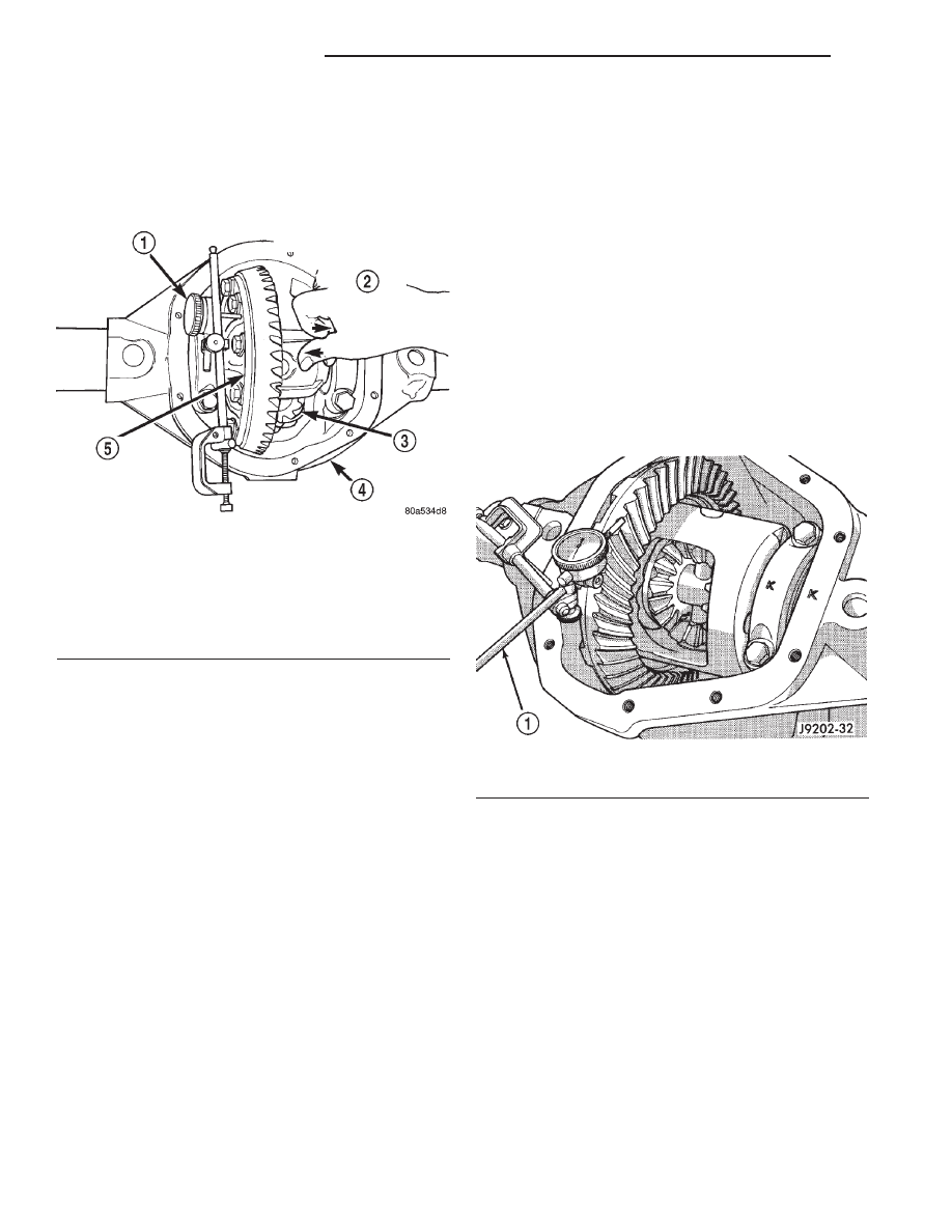
(24) Push and hold differential case to ring gear
side of the axle housing (Fig. 72).
(25) Record dial indicator reading (Fig. 72). Add
the starting point shim thickness to the dial indica-
tor reading to obtain the total shim thickness neces-
sary to achieve zero backlash.
(26) Subtract 0.003 in. (0.076 mm) from the dial
indicator reading to compensate for backlash between
ring and pinion gears. This total is the thickness
shim required to achieve proper backlash.
(27) Subtract the backlash shim thickness from
the total preload shim thickness. The remainder is
the shim thickness required on the pinion side of the
axle housing.
(28) Rotate dial indicator out of the way on guide
stud.
(29) Remove differential case and dummy bearings
from axle housing.
(30) Install side bearings and cups on differential
case.
(31) Install spreader W-129-B, utilizing some items
from Adapter Set 6987, on axle housing and spread
axle opening enough to receive differential case.
(32) Place the required differential bearing preload
shims in the axle housing against the axle tubes.
(33) Install differential case in axle housing.
(34) Remove spreader from axle housing.
(35) Rotate the differential case several times to
seat the side bearings.
(36) Position the indicator plunger against a ring
gear tooth (Fig. 73).
(37) Push and hold ring gear upward while not
allowing the pinion gear to rotate.
(38) Zero dial indicator face to pointer.
(39) Push and hold ring gear downward while not
allowing the pinion gear to rotate. Dial indicator
reading should be between 0.12 mm (0.005 in.) and
0.20 mm (0.008 in.). If backlash is not within specifi-
cations transfer the necessary amount of shim thick-
ness from one side of the axle housing to the other
(Fig. 74).
(40) Verify differential case and ring gear runout
by measuring ring to pinion gear backlash at eight
locations around the ring gear. Readings should not
vary more than 0.05 mm (0.002 in.). If readings vary
more than specified, the ring gear or the differential
case is defective.
After the proper backlash is achieved, perform
Gear Contact Pattern Analysis procedure.
DIFFERENTIAL TOTAL TORQUE TO ROTATE
(1) Rotate the pinion a minimum of ten times to
seat the differential bearings. Verify that the rotation
is smooth and repeatable.
(2) While rotating the pinion at a slow steady rate,
measure the differential total torque to rotate.
Record the value.
(3) The differential total torque to rotate must be
greater than the pinion torque to rotate plus 3 in.lbs.
for axles equipped with an standard differential. On
axles equipped with a Vari-Lok
y differential, the dif-
ferential total torque to rotate must be greater than
the pinion torque to rotate plus 6 in.lbs..
(4) The differential total torque to rotate must be
less than the pinion torque to rotate plus 11 in.lbs.
for axles equipped with an standard differential. On
axles equipped with a Vari-Lok
y differential, the dif-
Fig. 72 Hold Differential Case and Read Dial
Indicator
1 – READ DIAL INDICATOR
2 – FORCE DIFFERENTIAL CASE TO RING GEAR SIDE
3 – PINION GEAR
4 – AXLE HOUSING
5 – DIFFERENTIAL CASE
Fig. 73 Ring Gear Backlash Measurement
1 – DIAL INDICATOR
3 - 46
TUBE AND 186 FBI AXLE
WJ
ADJUSTMENTS (Continued)