Jeep Grand Cherokee WJ. Manual - part 23


  Index      Jeep     Jeep Grand Cherokee WJ - service repair manual 2001 year


Search            


Content   ..  21  22  23  24   ..


Jeep Grand Cherokee WJ. Manual - part 23


(12) Install differential assembly.

RING GEAR

NOTE: The ring gear and pinion are serviced as a
matched set. Do not replace the ring gear without
replacing the pinion.

REMOVAL

(1) Remove differential from axle housing.
(2) Place differential case in a suitable vise with

soft metal jaw protectors. (Fig. 51)

(3) Remove bolts holding ring gear to differential

case.

(4) Using a soft hammer, drive ring gear from dif-

ferential case (Fig. 51).

INSTALLATION

CAUTION: Do not reuse the bolts that held the ring
gear to the differential case. The bolts can fracture
causing extensive damage.

(1) Invert the differential case and start two ring

gear bolts. This will provide case-to-ring gear bolt
hole alignment.

(2) Invert the differential case in the vise.

(3) Install new ring gear bolts and alternately

tighten to 95–122 N·m (70–90 ft. lbs.) torque (Fig.
52).

(4) Install differential in axle housing and verify

gear mesh and contact pattern.

DISASSEMBLY AND ASSEMBLY

STANDARD DIFFERENTIAL

DISASSEMBLY

(1) Remove the ring gear.
(2) Using a suitable roll pin punch, drive out the

roll pin holding pinion gear mate shaft in the differ-
ential case (Fig. 53).

(3) Remove the pinion gear mate shaft from the

differential case and the pinion mate gears.

(4) Rotate differential side gears and remove the

pinion mate gears and thrust washers (Fig. 54).

(5) Remove the differential side gears and thrust

washers.

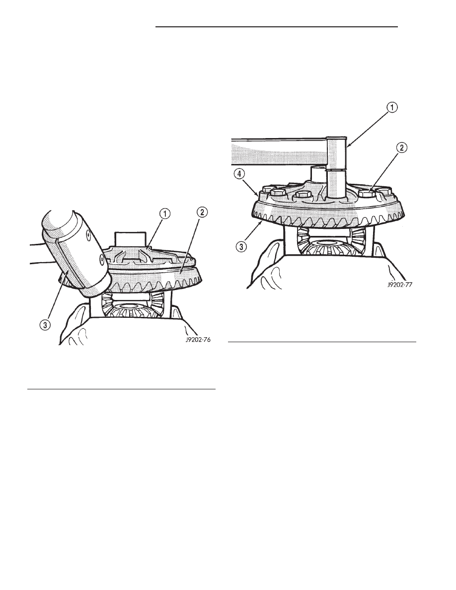
Fig. 51 Ring Gear Removal

1 – CASE
2 – RING GEAR
3 – RAWHIDE HAMMER

Fig. 52 Ring Gear Bolt Installation

1 – TORQUE WRENCH
2 – RING GEAR BOLT
3 – RING GEAR
4 – CASE

3 - 38

TUBE AND 186 FBI AXLE

WJ

REMOVAL AND INSTALLATION (Continued)

ASSEMBLY

(1) Install the differential side gears and thrust

washers.

(2) Install the pinion mate gears and thrust wash-

ers.

(3) Install the pinion gear mate shaft. Align the

roll pin holes in shaft and the differential case.

(4) Install the roll pin to hold the pinion mate

shaft in the differential case (Fig. 55).

(5) Install the ring gear.
(6) Lubricate

all

differential

components

with

hypoid gear lubricant.

FINAL ASSEMBLY

(1) Scrape the residual sealant from the housing

and cover mating surfaces. Clean the mating surfaces
with mineral spirits. Apply a bead of Mopar

t Silicone

Rubber Sealant, or equivalent, on the housing cover
(Fig. 56).

Install the housing cover within 5 minutes

after applying the sealant.

(2) Install the cover on the differential with the

attaching bolts. Install the identification tag. Tighten
the cover bolts to 41 N·m (30 ft. lbs.) torque.

CAUTION: Overfilling the differential can result in
lubricant foaming and overheating.

Fig. 53 Mate Shaft Roll Pin Removal

1 – DRIFT
2 – LOCKPIN
3 – MATE SHAFT

Fig. 54 Pinion Mate Gear Removal

1 – THRUST WASHER
2 – SIDE GEAR
3 – PINION MATE GEAR

Fig. 55 Mate Shaft Roll Pin Installation

1 – PUNCH
2 – PINION MATE SHAFT
3 – MATE SHAFT LOCKPIN

WJ

TUBE AND 186 FBI AXLE

3 - 39

DISASSEMBLY AND ASSEMBLY (Continued)

(3) Refill the differential housing with gear lubri-

cant. Refer to the Lubricant Specifications section of
this group for the gear lubricant requirements.

(4) Install the fill hole plug.

CLEANING AND INSPECTION

CARDAN U-JOINT

Clean all the U–joint yoke bores with cleaning sol-

vent and a wire brush. Ensure that all the rust and
foreign matter are removed from the bores.

Inspect the yokes for distortion, cracks and worn

bearing cap bores.

Replace the complete U–joint if any of the compo-

nents are defective.

AXLE COMPONENTS

Wash differential components with cleaning solvent

and dry with compressed air. Do not steam clean
the differential components.

Wash bearings with solvent and towel dry, or dry

with compressed air. DO NOT spin bearings with
compressed

air.

Cup

and

bearing

must

be

replaced as matched sets only.

Clean axle shaft tubes and oil channels in housing.
Inspect for;
• Smooth appearance with no broken/dented sur-

faces on the bearing rollers or the roller contact sur-
faces.

• Bearing cups must not be distorted or cracked.

• Machined surfaces should be smooth and with-

out any raised edges.

• Raised metal on shoulders of cup bores should

be removed with a hand stone.

• Wear and damage to pinion gear mate shaft,

pinion gears, side gears and thrust washers. Replace
as a matched set only.

• Ring and pinion gear for worn and chipped

teeth.

• Ring gear for damaged bolt threads. Replaced as

a matched set only.

• Pinion yoke for cracks, worn splines, pitted

areas, and a rough/corroded seal contact surface.
Repair or replace as necessary.

• Preload shims for damage and distortion. Install

new shims, if necessary.

ADJUSTMENTS

PINION GEAR DEPTH

GENERAL INFORMATION

Ring and pinion gears are supplied as matched

sets only. The identifying numbers for the ring and
pinion gear are etched into the face of each gear (Fig.
57). A plus (+) number, minus (–) number or zero (0)
is etched into the face of the pinion gear. This num-
ber is the amount (in thousandths of an inch) the
depth varies from the standard depth setting of a
pinion etched with a (0). The standard setting from
the center line of the ring gear to the back face of the
pinion is 92.08 mm (3.625 in.). The standard depth
provides the best gear tooth contact pattern. Refer to
Backlash and Contact Pattern Analysis paragraph in
this section for additional information.

Compensation

for

pinion

depth

variance

is

achieved with a select oil slinger/depth shim. The oil
slinger/depth shim is placed between the rear pinion
bearing cone and the pinion gear head (Fig. 58).

Fig. 56 Typical Housing Cover With Sealant

1 – SEALING SURFACE
2 – CONTOUR OF BEAD
3 – BEAD THICKNESS 6.35MM (1/4”)

3 - 40

TUBE AND 186 FBI AXLE

WJ

DISASSEMBLY AND ASSEMBLY (Continued)

If a new gear set is being installed, note the depth

variance etched into both the original and replace-
ment pinion gear. Add or subtract the thickness of
the original depth shims to compensate for the differ-
ence in the depth variances. Refer to the Depth Vari-
ance chart.

Note where Old and New Pinion Marking columns

intersect.

Intersecting

figure

represents

plus

or

minus the amount needed.

Note the etched number on the face of the drive

pinion gear (–1, –2, 0, +1, +2, etc.). The numbers rep-
resent thousands of an inch deviation from the stan-
dard. If the number is negative, add that value to the
required thickness of the depth shims. If the number
is positive, subtract that value from the thickness of
the depth shim. If the number is 0 no change is nec-
essary.

PINION DEPTH MEASUREMENT AND ADJUSTMENT

Measurements are taken with pinion bearings and

bearing cups installed in the axle housing. Take mea-
surements with Pinion Gauge Set 6774 and Dial
Indicator C-3339 (Fig. 59).

(1) Assemble Pinion Height Block 6739, Pinion

Block 6733, and rear pinion bearing onto Screw 6741
(Fig. 59).

(2) Insert assembled height gauge components,

rear bearing and screw into axle housing through
pinion bearing cups (Fig. 60).

(3) Install front pinion bearing cone and Cone-nut

6740 hand tight (Fig. 59).

(4) Place Arbor Disc 6732 on Arbor D-115-3 in posi-

tion in axle housing side bearing cradles (Fig. 61).
Install differential bearing caps on Arbor Discs and
tighten cap bolts to 41 N·m (30 ft. lbs.).

PINION GEAR DEPTH VARIANCE

Original Pinion

Gear Depth

Variance

Replacement Pinion Gear Depth Variance

−4

−3

−2

−1

0

+1

+2

+3

+4

+4

+0.008

+0.007

+0.006

+0.005

+0.004

+0.003

+0.002

+0.001

0

+3

+0.007

+0.006

+0.005

+0.004

+0.003

+0.002

+0.001

0

−0.001

+2

+0.006

+0.005

+0.004

+0.003

+0.002

+0.001

0

−0.001

−0.002

+1

+0.005

+0.004

+0.003

+0.002

+0.001

0

−0.001

−0.002

−0.003

0

+0.004

+0.003

+0.002

+0.001

0

−0.001

−0.002

−0.003

−0.004

−1

+0.003

+0.002

+0.001

0

−0.001

−0.002

−0.003

−0.004

−0.005

−2

+0.002

+0.001

0

−0.001

−0.002

−0.003

−0.004

−0.005

−0.006

−3

+0.001

0

−0.001

−0.002

−0.003

−0.004

−0.005

−0.006

−0.007

−4

0

−0.001

−0.002

−0.003

−0.004

−0.005

−0.006

−0.007

−0.008

Fig. 57 Pinion Gear ID Numbers

1 – PRODUCTION NUMBERS
2 – DRIVE PINION GEAR DEPTH VARIANCE
3 – GEAR MATCHING NUMBER (SAME AS RING GEAR

NUMBER)

Fig. 58 Shim Locations

1 – PINION GEAR DEPTH SHIM
2 – DIFFERENTIAL BEARING SHIM-PINION GEAR SIDE
3 – RING GEAR
4 – DIFFERENTIAL BEARING SHIM-RING GEAR SIDE
5 – COLLAPSIBLE SPACER

WJ

TUBE AND 186 FBI AXLE

3 - 41

ADJUSTMENTS (Continued)


Content   ..  21  22  23  24   ..