Jeep Grand Cherokee WJ. Manual - part 13


  Index      Jeep     Jeep Grand Cherokee WJ - service repair manual 2001 year


Search            


Content   ..  11  12  13  14   ..


Jeep Grand Cherokee WJ. Manual - part 13


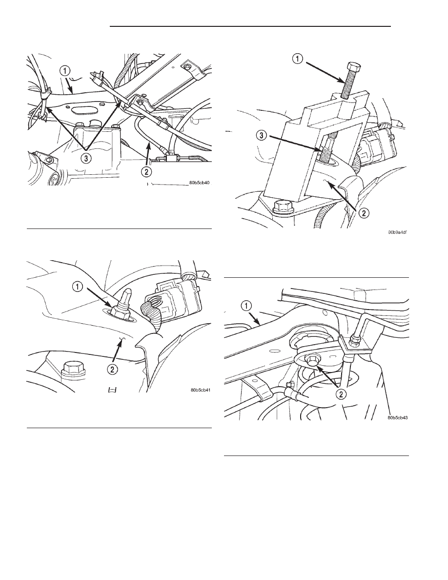
(4) Remove the ball joint nut from the top of the

upper suspension arm (Fig. 8).

(5) Separate ball joint from the arm with Remover

8278 (Fig. 9).

NOTE: It may be necessary to strike the upper con-
trol arm with a hammer to separate the ball joint
from the arm.

(6) Remove the upper suspension arm mounting

bolts and remove the arm (Fig. 10).

INSTALLATION

(1) Position the upper suspension arm in the

frame rail brackets.

(2) Install the mounting bolts and tighten to 100

N·m (74 ft. lbs.).

(3) Pull the arm down on the ball joint stud and

install a new nut. Tighten the nut to 142 N·m (105
ft. lbs.).

(4) Install the park brake cables and brake hose to

the arm.

(5) Remove the supports and lower the vehicle.

Fig. 7 Park Brake Cables And Brake Hose

1 – UPPER SUSPENSION ARM
2 – REAR BRAKE HOSE
3 – PARK BRAKE CABLES

Fig. 8 Ball Joint Nut

1 – BALL JOINT NUT
2 – UPPER SUSPENSION ARM

Fig. 9 Separate Ball Joint

1 – REMOVER
2 – UPPER SUSPENSION ARM
3 – BALL JOINT STUD

Fig. 10 Upper Suspension Arm Mounting Bolt

1 – UPPER SUSPENSION ARM
2 – MOUNTING BOLT

2 - 20

SUSPENSION

WJ

REMOVAL AND INSTALLATION (Continued)

BALL JOINT

REMOVAL

(1) Raise and support the vehicle.
(2) Support the rear axle with a hydraulic jack.
(3) Remove the ball joint nut from the top of the

upper suspension arm (Fig. 11).

(4) Separate ball joint from the arm with Remover

8278 (Fig. 12).

NOTE: It may be necessary to strike the upper con-
trol arm with a hammer to separate the ball joint
from the arm.

(5) Remove the ball joint mounting bolts (Fig. 13)

from the differential housing.

(6) Remove the ball joint from the differential

housing.

INSTALLATION

(1) Install the ball joint on the differential hous-

ing.

(2) Install the ball joint mounting bolts and

tighten to 136 N·m (100 ft. lbs.).

(3) Raise the rear axle with a hydraulic jack to

align the upper arm with the ball joint.

(4) Pull the arm down on the ball joint stud and

install a new nut. Tighten the nut to 142 N·m (105
ft. lbs.).

(5) Remove the supports and lower the vehicle.

STABILIZER BAR

REMOVAL

(1) Raise and support the vehicle.

(2) Remove the stabilizer bar links from stabilizer

bar and frame mount. (Fig. 14).

(3) Remove the stabilizer bar retainer bolts.
(4) Remove the stabilizer bar.

Fig. 11 Ball Joint Nut

1 – BALL JOINT NUT
2 – UPPER SUSPENSION ARM

Fig. 12 Separate Ball Joint

1 – REMOVER
2 – UPPER SUSPENSION ARM
3 – BALL JOINT STUD

Fig. 13 Ball Joint Mounting Bolts

1 – BALL JOINT
2 – MOUNTING BOLTS

WJ

SUSPENSION

2 - 21

REMOVAL AND INSTALLATION (Continued)

INSTALLATION

(1) Position the stabilizer bar on the axle and

install the retainers and bolts. Ensure the bar is cen-
tered with equal spacing on both sides. Tighten the
bolts to 54 N·m (40 ft. lbs.).

(2) Install the links to the stabilizer bar and frame

brackets.

(3) Tighten the nuts at the stabilizer bar to 54

N·m (40 ft. lbs.).

(4) Tighten the nuts at the frame brackets to 92

N·m (68 ft. lbs.).

(5) Remove support and lower the vehicle.

SPECIFICATIONS

TORQUE CHART

DESCRIPTION

TORQUE

Shock Absorber

Upper Nut . . . . . . . . . . . . . . 108 N·m (80 ft. lbs.)
Lower Nut . . . . . . . . . . . . . . 115 N·m (85 ft. lbs.)

Suspension Arm Upper

Ball Joint Nut . . . . . . . . . . 142 N·m (105 ft. lbs.)
Frame Bolts . . . . . . . . . . . . . 100 N·m (74 ft. lbs.)

Ball Joint

Plate Bolts . . . . . . . . . . . . . 136 N·m (100 ft. lbs.)

Suspension Arms Lower

Axle Bracket Nut . . . . . . . . 163 N·m (120 ft. lbs.)
Frame Bracket Nut . . . . . . 156 N·m (115 ft. lbs.)

Stabilizer Bar

Retainer Bolts . . . . . . . . . . . . 54 N·m (40 ft. lbs.)
Bar Link Nut . . . . . . . . . . . . . 54 N·m (40 ft. lbs.)
Bracket Link Nut . . . . . . . . . . 92 N·m (68 ft. lbs.)

SPECIAL TOOLS

REAR SUSPENSION

Fig. 14 Rear Stabilizer Bar

1 – LINK
2 – RETAINER
3 – BUSHING
4 – STABILIZER BAR

Remover 8278

2 - 22

SUSPENSION

WJ

REMOVAL AND INSTALLATION (Continued)

DIFFERENTIAL AND DRIVELINE

TABLE OF CONTENTS

page

page

PROPELLER SHAFTS . . . . . . . . . . . . . . . . . . . . . . . 1
TUBE AND 186 FBI AXLE . . . . . . . . . . . . . . . . . . . 1
1

198 RBI AXLE . . . . . . . . . . . . . . . . . . . . . . . . . . . . 53
226 RBA AXLE . . . . . . . . . . . . . . . . . . . . . . . . . . . 9
5

PROPELLER SHAFTS

TABLE OF CONTENTS

page

page

DESCRIPTION AND OPERATION

PROPELLER SHAFTS . . . . . . . . . . . . . . . . . . . . . . 1
PROPELLER SHAFT JOINTS . . . . . . . . . . . . . . . . . 2
PROPELLER SHAFT JOINT ANGLE . . . . . . . . . . . . 2

DIAGNOSIS AND TESTING

VIBRATION . . . . . . . . . . . . . . . . . . . . . . . . . . . . . . 2
UNBALANCE . . . . . . . . . . . . . . . . . . . . . . . . . . . . . 3
RUNOUT . . . . . . . . . . . . . . . . . . . . . . . . . . . . . . . . 5

SERVICE PROCEDURES

DRIVELINE ANGLE MEASUREMENT

PREPARATION . . . . . . . . . . . . . . . . . . . . . . . . . . 5

PROPELLER SHAFT ANGLE MEASUREMENT. . . . 6

REMOVAL AND INSTALLATION

FRONT PROPELLER SHAFT . . . . . . . . . . . . . . . . . 6

REAR PROPELLER SHAFT . . . . . . . . . . . . . . . . . . 8

DISASSEMBLY AND ASSEMBLY

SINGLE CARDAN UNIVERSAL JOINT . . . . . . . . . . 8

CLEANING AND INSPECTION

SINGLE CARDAN JOINT . . . . . . . . . . . . . . . . . . . 10

ADJUSTMENTS

FRONT PROPELLER SHAFT MEASUREMENT . . 10

SPECIFICATIONS

TORQUE . . . . . . . . . . . . . . . . . . . . . . . . . . . . . . . 10

SPECIAL TOOLS

PROPELLER SHAFT . . . . . . . . . . . . . . . . . . . . . . 10

DESCRIPTION AND OPERATION

PROPELLER SHAFTS

DESCRIPTION

A propeller shaft (Fig. 2) is the shaft which con-

nects the transmission/transfer case to the axle dif-
ferential. This is the link through which the engine
power is transmitted to the axle.

The propeller shaft is designed and built with the

yoke lugs in line with each other which is called zero
phasing. This design produces the smoothest running
condition, an out-of-phase shaft can cause a vibra-
tion.

Tubular propeller shafts are balanced by the man-

ufacturer with weights spot welded to the tube.

FRONT PROPELLER SHAFT

Only one style of front propeller shaft is used on

WJ vehicles. The propeller shaft uses a Constant

Velocity (CV) joint at both the axle and transfer case
end of the propeller shaft. The CV joint at the axle
end contracts and extends (plunges) as necessary to
accomadate the variations in length necessary due to
suspension travel. The CV joint at the transfer case
end of the propeller shaft is fixed. The two CV joints
are connected by a hollow tube shaft. The shaft
length is not adjustable and does vary according to
application.

PRECAUTIONS

Use the exact replacement parts when installing

the propeller shafts. The use of the correct replace-
ment parts helps to ensure safe operation. All fasten-
ers must be torqued to the specified values for safe
operation.

Also make alignment reference marks (Fig. 1) on

the propeller shaft yoke and axle, or transmission,
yoke prior to servicing. This helps to eliminate possi-
ble vibration.

WJ

DIFFERENTIAL AND DRIVELINE

3 - 1


Content   ..  11  12  13  14   ..