Jeep Grand Cherokee WJ. Manual - part 11
(4) With the vehicle on the ground tighten the axle
bracket nut and the frame bracket bolt to 61 N·m (45
ft. lbs.).
(5) Check
the
alignment
if
new
parts
were
installed.
FRONT AXLE BUSHING
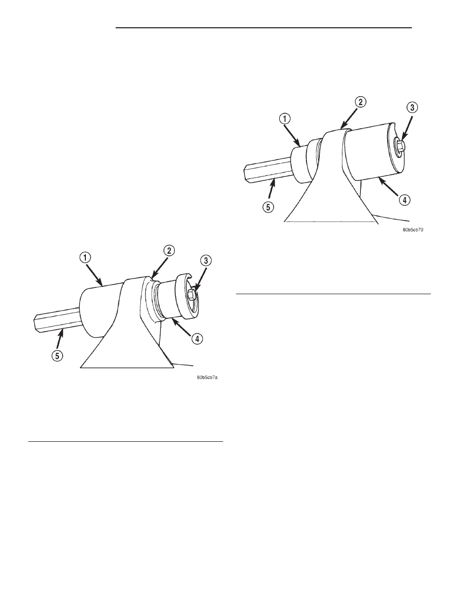
REMOVAL
(1) Remove the upper suspension arm from axle.
(2) Position Spacer 8279 over the axle bushing on
a 4x2 vehicle and right side on a 4x4 vehicle.
(3) Place Receiver 7932-1 over flanged end of the
bushing. (Fig. 9).
(4) Place small end of Remover/Install 7932-2
against other side of the bushing.
(5) Install bolt 7604 through remover, bushing and
receiver.
(6) Install Long Nut 7603 and tighten nut too pull
bushing out of the axle bracket.
(7) Remove nut, bolt, receiver, remover and bush-
ing.
NOTE: On 4x2 vehicle and right side of 4x4 vehicle,
leave Spacer 8279 in position for bushing installa-
tion.
INSTALLATION
(1) Place Receiver 7932-1on the other side of the
axle bracket.
(2) Position new bushing up to the axle bracket.,
and large end of Remover/Install 7932-2 against the
bushing (Fig. 10).
(3) Install bolt 7604 through receiver, bushing and
installer.
(4) Install Long Nut 7603 and tighten nut to draw
the bushing into the axle bracket.
(5) Remove tools and install the upper suspension
arm.
STABILIZER BAR
REMOVAL
(1) Raise and support the vehicle.
(2) Remove link nuts and bolts (Fig. 11) and
remove the links.
(3) Remove the stabilizer bar retainer bolts (Fig.
11) from the frame rails and remove the stabilizer
bar.
INSTALLATION
(1) Position the stabilizer bar on the frame rail
and install the retainers and bolts. Ensure the bar is
centered with equal spacing on both sides. Tighten
the bolts to 92 N·m (68 ft. lbs.).
(2) Install the links onto the stabilizer bar and
axle brackets and install the bolts and nuts finger
tight.
(3) Remove the supports and lower the vehicle.
(4) With the vehicle on the ground tighten the sta-
bilizer bar link nuts to 106 N·m (78 ft. lbs.).
TRACK BAR
REMOVAL
(1) Raise and support the vehicle.
Fig. 9 Bushing Removal
1 – RECEIVER
2 – AXLE BRACKET
3 – BOLT
4 – REMOVER/INSTALLER
5 – LONG NUT
Fig. 10 Bushing Installation
1 – REMOVER/INSTALLER
2 – AXLE BRACKET
3 – BOLT
4 – RECEIVER
5 – LONG NUT
2 - 12
SUSPENSION
WJ
REMOVAL AND INSTALLATION (Continued)