Jaguar X-Type Sedan and Estate (Wagon). Manual - part 463
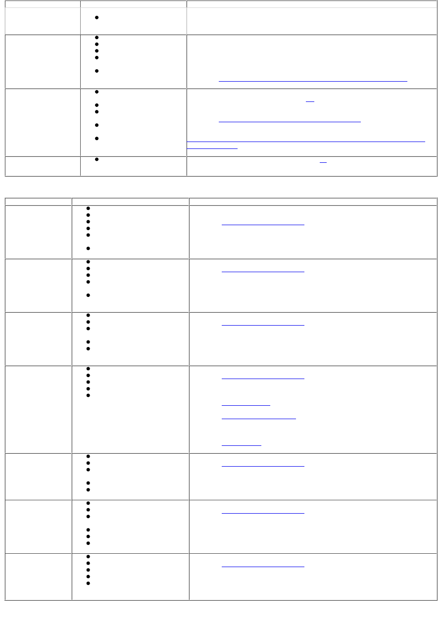
Symptom
Possible source
Action
canister
Snow or ice pack around
the canister outlet or filter
Fuel smells in/around
the vehicle
Filler cap incorrectly fitted
Leaks from joints
Leaks from module seals
Leak from inlet/outlet
pipes at purge valve
Inoperative purge valve
Check that the filler cap is correctly fitted and secure (the filler cap must be
tightened to at least three 'clicks'). Inspect the pipes and joints for evidence of
leakage, using an HC detector. Inspect the fuel tank for evidence indicating a
leak from the module seals. If such evidence is found, the fuel tank should be
removed to check the seals. Check for DTCs indicating an evaporative emissions
system purge valve malfunction. For evaporative emissions system tests,
REFER to:
Evaporative Emissions - 2.5L NA V6 - AJV6/3.0L NA V6 - AJ27
(303-13
Evaporative Emissions, Diagnosis and Testing).
Engine stops with fuel
indicated on the gauge
Fuel transfer malfunction
(2.5/3.0 L only)
Level sensor malfunction
Transfer pipes split/kinked
(2.5/3.0 L only)
Blocked transfer pump
module jet (2.5/3.0 L only)
Non fuel-related fault
Check for DTCs indicating a failure to transfer fuel, refer to the DTC index. For
fuel transfer test, GO to Pinpoint Test
C.
Check the internal transfer pipes for
damage/kinking. Check the 2mm hole as detailed in bulletin A310-01. Check for
DTCs indicating a non fuel-related fault. For a full list of DTCs,
REFER to:
Electronic Engine Controls - 2.0L NA V6 - AJV6
(303-14A Electronic
Engine Controls - 2.0L NA V6 - AJV6/2.5L NA V6 - AJV6/3.0L NA V6 - AJ27,
Diagnosis and Testing) /
Electronic Engine Controls - 2.5L NA V6 - AJV6/3.0L NA V6 - AJ27, VIN Range:
E96603->J28492
(303-14A Electronic Engine Controls - 2.0L NA V6 - AJV6/2.5L
NA V6 - AJV6/3.0L NA V6 - AJ27, Diagnosis and Testing).
Fuel pump noise
Fuel pump module
malfunction
For a basic noise test, GO to Pinpoint Test
D.
Symptom chart (vehicles with diesel engine only)
Symptom
Possible source
Action
Engine cranks, but
does not start
IFS switch
Low/contaminated fuel
Blocked fuel filter
Low pressure circuit fault
Fuel metering valve
blocked/contaminated
Pump failure
Check that the inertia switch has not tripped. Check fuel level/condition. For
fuel system tests,
REFER to:
Fuel Charging and Controls
(303-04B Fuel Charging and Controls -
2.0L Duratorq-TDCi/2.2L Duratorq-TDCi (110kW /150PS) - Puma, Diagnosis and
Testing).
Difficult to start
Low/contaminated fuel
Blocked fuel filter
Low pressure circuit fault
Fuel metering valve
blocked/contaminated
Injector(s)
failure/programming
Check fuel level/condition. For fuel system tests,
REFER to:
Fuel Charging and Controls
(303-04B Fuel Charging and Controls -
2.0L Duratorq-TDCi/2.2L Duratorq-TDCi (110kW /150PS) - Puma, Diagnosis and
Testing).
Check the injector programming using the Jaguar approved diagnostic system.
Rough idle
Low/contaminated fuel
Blocked fuel filter
Fuel metering valve
blocked/contaminated
Low pressure circuit fault
Injector(s)
failure/programming
Check fuel level/condition. For fuel system tests,
REFER to:
Fuel Charging and Controls
(303-04B Fuel Charging and Controls -
2.0L Duratorq-TDCi/2.2L Duratorq-TDCi (110kW /150PS) - Puma, Diagnosis and
Testing).
Check the injector programming using the Jaguar approved diagnostic system.
Lack of power when
accelerating
Air intake circuit fault
Catalyst blocked
Low fuel pressure
EGR valve fault
Turbocharger fault
For fuel system tests,
REFER to:
Fuel Charging and Controls
(303-04B Fuel Charging and Controls -
2.0L Duratorq-TDCi/2.2L Duratorq-TDCi (110kW /150PS) - Puma, Diagnosis and
Testing).
For exhaust system tests,
REFER to:
Exhaust System
(309-00 Exhaust System, Diagnosis and Testing).
For EGR tests,
REFER to:
Engine Emission Control
(303-08 Engine Emission Control - 2.0L
Duratorq-TDCi/2.2L Duratorq-TDCi (110kW/150PS) - Puma, Diagnosis and
Testing).
For turbocharger tests,
REFER to:
Turbocharger
(303-04C Fuel Charging and Controls - Turbocharger,
Diagnosis and Testing).
Engine stops/stalls
Low/contaminated fuel
Low pressure circuit fault
Fuel metering valve
blocked/contaminated
Fuel metering valve leak
High pressure leak
Check fuel level/condition. For fuel system tests,
REFER to:
Fuel Charging and Controls
(303-04B Fuel Charging and Controls -
2.0L Duratorq-TDCi/2.2L Duratorq-TDCi (110kW /150PS) - Puma, Diagnosis and
Testing).
Engine judders
Low/contaminated fuel
Low pressure circuit fault
Fuel metering valve
blocked/contaminated
Fuel metering valve leak
High pressure leak
Pump fault
Check fuel level/condition. For fuel system tests,
REFER to:
Fuel Charging and Controls
(303-04B Fuel Charging and Controls -
2.0L Duratorq-TDCi/2.2L Duratorq-TDCi (110kW /150PS) - Puma, Diagnosis and
Testing).
Excessive fuel
consumption
Low pressure circuit fault
Fuel metering valve leak
Fuel temperature sensor leak
High pressure leak
Injector(s)
failure/programming
Check fuel level/condition. For fuel system tests,
REFER to:
Fuel Charging and Controls
(303-04B Fuel Charging and Controls -
2.0L Duratorq-TDCi/2.2L Duratorq-TDCi (110kW /150PS) - Puma, Diagnosis and
Testing).
DTC index (for a full list of DTCs for both petrol and diesel engines, refer to sections 303.14 A or B)