Jaguar X-Type Sedan and Estate (Wagon). Manual - part 456


  Index      Jaguar     Jaguar X-Type Sedan and Estate (Wagon) (2.0 L, 2.5 L and 3.0 L Gasoline; 2.0 L and 2.2 L, Diesel) - manual 2001-2009 year


Search            


Content   ..  454  455  456  457   ..


Jaguar X-Type Sedan and Estate (Wagon). Manual - part 456


*
*
*
*
*

*

*
*
*
*
*

*
*

*

Published: 11-May-2011

Fuel System - General Information - Fuel System

Diagnosis and Testing

1. Verify the customer concern.

1.

2. Visually inspect for obvious signs of mechanical or electrical damage.

2.

3. If an obvious cause for an observed or reported concern is found, correct the cause (if possible) before proceeding to the next

step.

3.

4. If the concern is not visually evident, refer to the Symptom Chart.

4.

Symptom Chart

Symptom

Possible Sources

Action

P1233, P1235, —Fuel Pump Primary
Circuit Failure

Damaged harness.
Connector loose or corroded.
Connector pin(s) bent or tracking between connections.
Damaged GROUND.
'Popped' inertia switch.

GO to Pinpoint
Test 

A.

B1201, P0460, —Fuel Sender Circuit
Failure

W orn or damaged sensor tracks.
Damaged Harness.
Connector loose or corroded.
Connector pin(s) bent or tracking between connections.
Fuel level sensor to instrument cluster circuits intermittent short or open
circuit or high resistance.
Fuel level sensor failure.
Instrument cluster fault (incorrect fuel level data).

GO to Pinpoint
Test 

B.

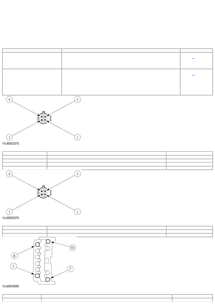
Fuel Pump Harness Connector

Pin Number

Circuit Function

Circuit Color

1

Fuel level sensor signal supply

Yellow/white

2

Fuel pump voltage supply

Pink/black

3

Fuel level sensor GROUND supply

Pink/orange

4

Fuel pump GROUND supply

Black

Transfer Pump Fuel Level Sensor Harness Connector

Pin Number

Circuit Function

Circuit Color

1

Fuel level sensor signal supply

Yellow/white

3

Fuel level sensor GROUND supply

Pink/orange

Fuel Pump Controller Harness Connector

Pin Number

Circuit Function

Circuit Color

1

engine control module (ECM) control input

Brown

1
2
3
4

1
2

1
2

1

1
2
3
4

1

1
2

1

1

Pin Number

Circuit Function

Circuit Color

2

Ground

Black

3

Fuel pump ground

Yellow

4

Throttle screen

Black/green

5

Fuel pump screen

White

7

ECM monitor output

White

9

Battery positive

Brown/green

10

Fuel pump positive

Red

PINPOINT TEST A : P1233, P1235—FUEL PUMP PRIMARY CIRCUIT FAILURE

TEST

CONDITIONS

DETAILS/RESULTS/ACTIONS

A1: CHECK THE POSITIVE SUPPLY TO THE FUEL PUMP

Switch the ignition to the OFF position.
Disconnect the fuel pump electrical connector FT002.
Switch the ignition to the RUN position.
Measure the pulse width modulation voltage between the fuel pump electrical connector FT002 pin 2, (KB) and
GROUND.

Is there a 1 second, 12 volts voltage signal after the ignition is switched on?
Yes

GO to A2

.

No

GO to A5

.

A2: CHECK THE GROUND SUPPLY TO THE FUEL PUMP

Switch the ignition to the OFF position.
Measure the resistance between the fuel pump electrical connector FT002 pin 4, (B) and GROUND.

Is the resistance less than 0.5 Ohm?
Yes

INSTALL a new fuel pump. CLEAR DTC. TEST the system for normal operation.

No

GO to A7

.

A3: CHECK THE POSITIVE SUPPLY TO THE FUEL PUMP CONTROLLER

Switch the ignition to the RUN position.
Measure the voltage at the fuel pump controller CA105 pin 9.

Is the voltage less than 10.5 Volts?
Yes

GO to A4

.

No

GO to A10

.

A4: CHECK THE FUEL PUMP CONTROLLER VOLTAGE SUPPLY FUSE

Measure the voltage at the fuel pump controller supply fuse.

Is the voltage less than 10.5 Volts?
Yes

GO to A12

.

No

REPAIR the circuit between the central electrical junction box (CEJB) and the fuel pump controller. CLEAR DTC. TEST
the system for normal operation.

A5: CHECK THE VOLTAGE OUTPUT AT THE FUEL PUMP CONTROLLER

Switch the ignition to the OFF position.
Disconnect the fuel pump controller electrical connector CA105.
Switch the ignition to the RUN position.
Measure the pulse width modulation voltage between the fuel pump controller electrical connector CA105 pin 10 and
GROUND.

Is there a 1 second 12 volts voltage signal after the ignition is switched on?
Yes

GO to A6

. .

No

GO to A3

. .

A6: CHECK THE CONTINUITY BETWEEN THE FUEL PUMP CONTROLLER AND THE FUEL PUMP

Measure the resistance between the fuel pump controller connector CA105 pin 10, (R) and fuel pump electrical
connector FT002 pin 2, (KB).

Is the resistance less than 0.5 Ohm?
Yes

INSTALL a new fuel pump controller. CLEAR DTC. TEST the system for normal operation.

No

REPAIR the circuit between the fuel pump controller CA105 pin 10, (R) and the fuel pump electrical connector FT002
pin 2, (KB). CLEAR DTC. TEST the system for normal operation.

A7: CHECK THE GROUND SUPPLY AT THE FUEL PUMP CONTROLLER

Switch the ignition to the OFF position.
Measure the resistance between the fuel pump controller electrical connector CA105 pin 3, (Y) and GROUND.

Is the resistance less than 0.5 Ohm?
Yes

GO to A8

. .

No

GO to A9

. .

A8: CHECK THE CONTINUITY BETWEEN THE FUEL PUMP AND THE FUEL PUMP CONTROLLER

Measure the resistance between the fuel pump connector FT002 pin 4, (B) and the fuel pump controller connector
CA105 pin 3 (Y).

Is the resistance less than 0.5 Ohms?
Yes

GO to A9

.

No

REPAIR the circuit between the fuel pump FT002 pin 4, (B) and the fuel pump controller CA105 pin 3, (Y). CLEAR DTC.
TEST the system for normal operation.

A9: CHECK THE GROUND SUPPLY TO THE FUEL PUMP CONTROLLER

Switch the ignition to the OFF position.

2

1
2
3
4

1
2
3

1
2
3
4

1
2
3
4

1
2
3
4

1
2

1
2
3
4

Measure the resistance between the fuel pump controller CA105 pin 2, and GROUND.

Is the resistance less than 0.5 Ohm?
Yes

REPAIR the circuit between the fuel pump controller CA105 pin 2, (B) and GROUND. CLEAR DTC. TEST the system for
normal operation.

No

INSTALL a new fuel pump controller. CLEAR DTC. TEST the system for normal operation.

A10: CHECK THE SWITCHABLE SUPPLY TO THE FUEL PUMP CONTROLLER

Switch the ignition to the OFF position.
Disconnect the fuel pump controller electrical connector CA105.
Switch the ignition to the RUN position.
Measure the pulse width modulation frequency between the fuel pump controller electrical connector CA105 pin 1, (N)
and GROUND.

Is the frequency 250 Hz, 1-50% duty?
Yes

INSTALL a new fuel pump controller. CLEAR DTC. TEST the system for normal operation.

No

GO to A11

.

A11: CHECK THE CONTINUITY BETWEEN THE FUEL PUMP CONTROLLER AND THE ECM

Switch the ignition to the OFF position.
Disconnect the ECM electrical connector EN016.
Measure the resistance between the fuel pump controller electrical connector CA105 pin 1, (N) and the ECM electrical
connector EN106 pin 27, (N).

Is the resistance less than 0.5 Ohm?
Yes

INSTALL a new ECM. CLEAR DTC. TEST the system for normal operation.

No

REPAIR the circuit between the fuel pump controller electrical connector CA105 pin 1, (N) and the ECM electrical
connector EN106 pin 27, (N). CLEAR DTC. TEST the system for normal operation.

A12: CHECK THE POSITIVE SUPPLY TO THE IGNITION RELAY

Switch the ignition to the OFF position.
Disconnect the central electrical junction box (CEJB) electrical connector IP003.
Switch the ignition to the RUN position.
Measure the voltage between the CEJB electrical connector IP003 pin 1, (GU) and GROUND.

Is the voltage less than 10.5 Volts?
Yes

GO to A13

.

No

INSTALL a new ignition relay R18. CLEAR DTC. TEST the system for normal operation.

A13: CHECK THE POSITIVE SUPPLY TO THE INERTIA SWITCH

Switch the ignition to the OFF position.
Disconnect the inertia switch electrical connector IP132.
Switch the ignition to the RUN position.
Measure the voltage between the inertia switch electrical connector IP132 pin 3, (GO) and GROUND.

Is the voltage less than 10.5 Volts?
Yes

GO to A14

.

No

GO to A15

.

A14: CHECK THE INERTIA SWITCH VOLTAGE SUPPLY AT THE IGNITION SWITCH

Switch the ignition to the OFF position.
Remove the ignition switch electrical connector IP018.
Switch the ignition to the RUN position.
Measure the voltage between the ignition switch electrical connector IP018 pin 1 and GROUND.

Is the voltage less than 10.5 Volts?
Yes

INSTALL a new ignition switch. CLEAR DTC. TEST the system for normal operation.

No

REPAIR the circuit between the ignition switch and the inertia switch. CLEAR DTC. TEST system for normal operation.

A15: CHECK THE CONTINUITY BETWEEN THE CEJB AND THE INERTIA SWITCH

Switch the ignition switch to the OFF position.
Measure the resistance between the CEJB electrical connector IP003 pin 1, (GU) and the inertia switch electrical
connector IP132 pin 1, (GU).

Is the resistance less than 0.5 Ohm?
Yes

INSTALL a new inertia switch. CLEAR DTC. TEST the system for normal operation.

No

REPAIR the circuit between the CEJB electrical connector IP003 pin 1, (GU) and the inertia switch electrical connector
IP132 pin 1, (GU). CLEAR DTC. TEST the system for normal operation.

PINPOINT TEST B : B1201, P0460—FUEL SENDER CIRCUIT FAILURE

TEST

CONDITIONS

DETAILS/RESULTS/ACTIONS

B1: CHECK THE VOLTAGE SUPPLY TO THE FUEL TANK ELECTRICAL CONNECTOR

Switch the ignition to the OFF position.
Disconnect the fuel tank electrical connector CA005.
Switch the ignition to the RUN position.
Measure the voltage at the fuel tank electrical connector between:

CA005 pin 1, (W U) and GROUND
CA005 pin 2, (W B) and GROUND

1
2

1
2
3
4

1
2

3

1
2

Is the voltage greater than 10.5 Volts?
Yes

GO to B2

.

No

GO to B3

.

B2: CHECK THE GROUND SUPPLY TO THE FUEL TANK ELECTRICAL CONNECTOR

Switch the ignition to the OFF position.
Measure the resistance at the fuel tank electrical connector between CA005 pin 3, (B) and GROUND.

Is the resistance less than 0.5 Ohms?
Yes

GO to B4

.

No

GO to B5

.

B3: CHECK THE VOLTAGE SUPPLY FROM THE INSTRUMENT CLUSTER

Switch the ignition to the OFF position.
Disconnect the instrument cluster electrical connector IP010.
Switch the ignition switch to the RUN position.
Measure the voltage at the instrument cluster connector between:

IP010 pin 8 and GROUND
IP010 pin 7 and GROUND

Is the voltage greater than 10.5 Volts?
Yes

REPAIR the relevant circuit. CLEAR DTC. TEST the system for normal operation.

No

INSTALL a new instrument cluster. CLEAR DTC. TEST the system for normal operation.

B4: CHECK THE RESISTANCE AT THE FUEL LEVEL SENSORS

Remove the fuel tank. For additional information, refer to Section

 310-01 Fuel Tank and Lines

.

Disconnect the fuel sensor electrical connectors:

FT002
FT003

Measure the resistance between the sensor electrical connectors:

FT002 pin 1 and FT002 pin 3
FT003 pin 1 and FT003 pin 3

Is the resistance between 16 and 160 Ohms?
Yes

REPAIR the relevant circuit. CLEAR DTC. TEST the system for normal operation.

No

INSTALL the relevant new fuel level sensor. CLEAR DTC. TEST the system for normal operation.

B5: CHECK THE GROUND SUPPLY FROM THE INSTRUMENT CLUSTER

Disconnect the instrument cluster electrical connector IP010.
Measure the resistance at the instrument cluster between IP010 pin 9 and GROUND.

Is the resistance less than 0.5 Ohm?
Yes

REPAIR the circuit between the instrument cluster IP010 pin 9, (B) and the fuel tank electrical connector CA005 pin
3, (B). CLEAR DTC. TEST the system for normal operation.

No

INSTALL a new instrument cluster. CLEAR DTC. TEST the system for normal operation.


Content   ..  454  455  456  457   ..