Jaguar X-Type Sedan and Estate (Wagon). Manual - part 355
Item
Part Number
Description
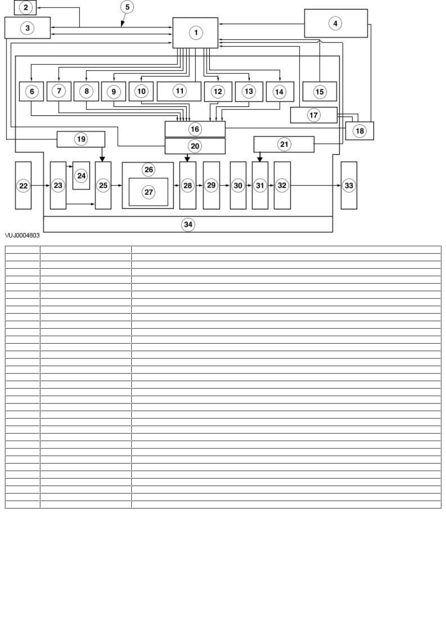
1
—
TCM
2
—
Anti-lock Braking System (ABS)
3
—
Engine Control Module (ECM)
4
—
D/4 switch, (test switch), sports mode switch
5
—
CAN (including torque down switch)
6
—
Line pressure solenoid
7
—
Lock-up solenoid
8
—
Shift solenoid A
9
—
Shift solenoid B
10
—
Shift solenoid C
11
—
Low clutch timing solenoid
12
—
Reduction timing solenoid
13
—
2-4 brake timing solenoid
14
—
2-4 brake duty solenoid
15
—
Transmission Fluid Temperature (TFT) sensor
16
—
Control valve
17
—
Inhibitor switch
18
—
Select lever
19
—
Turbine Shaft Speed (TSS) sensor
20
—
Intermediate Shaft Speed (ISS) sensor
21
—
Vehicle Speed (VSS) sensor
22
—
Engine
23
—
Torque converter
24
—
Fluid pump
25
—
Input shaft
26
—
Four-speed geartrain
27
—
Clutch, brake, planetary gear etc
28
—
Output gear
29
—
Idler gear
30
—
Reduction geartrain
31
—
Parking gear
32
—
Final gear and differential
33
—
Transfer case
34
—
Automatic transmission assembly
The transmission gear changes, oil pressure and lock-up operation are all electronically controlled. The TCM located in the left hand A-pillar
receives electrical signals from sensors indicating vehicle speed and throttle opening. In response to these signals the TCM selects the
appropriate gear and regulates other related conditions.
Actual transmission control changes are made by actuators (solenoids) that respond to input signals received from the TCM. These
solenoids operate in response to electrical signals they regulate the control valve operation. The control valves cause changes in the fluid
flow passages. This results in pressure changes within the transmission.
Transmission Construction
A cross-sectional view of the automatic transmission.