Jaguar X-Type Sedan and Estate (Wagon). Manual - part 339


  Index      Jaguar     Jaguar X-Type Sedan and Estate (Wagon) (2.0 L, 2.5 L and 3.0 L Gasoline; 2.0 L and 2.2 L, Diesel) - manual 2001-2009 year


Search            


Content   ..  337  338  339  340   ..


Jaguar X-Type Sedan and Estate (Wagon). Manual - part 339


8. CAUTIONS:

 Do not cut the HO2S harness.

 Make sure that the catalyst monitor sensor casing and cable are not

damaged.

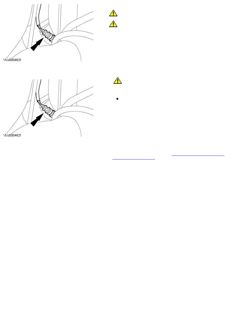
Using Snap-on socket YA8875 remove the catalyst monitor sensor.

Installation

1. 

CAUTION: Make sure that the catalyst monitor sensor casing and

cable are not damaged.

To install, reverse the removal procedure.

Tighten to 40 Nm.

2. NOTE: For NAS vehicles only.

If required, carry out a long drive cycle.
For additional information, refer to: 

Powertrain Control Module (PCM)

Long Drive Cycle Self-Test

 (303-14A Electronic Engine Controls - 2.0L NA

V6 - AJV6/2.5L NA V6 - AJV6/3.0L NA V6 - AJ27, General Procedures).

Published: 11-May-2011

Electronic Engine Controls - 2.0L NA V6 - AJV6/2.5L NA V6 - AJV6/3.0L NA V6 - AJ27 -
Crankshaft Position (CKP) Sensor

Removal and Installation

Removal

1. Remove the right-hand front road wheel. For additional information,

refer to Section

 204-04 W heels and Tires

.

2. Remove the wheel arch liner access cover.

3. Disconnect the CKP sensor electrical connector.

4. Remove the CKP sensor.

Remove and discard the O-ring seal.

Installation

1. NOTE: Install a new O-ring seal.

To install, reverse the removal procedure.

Tighten to 10 Nm.

Published: 11-May-2011

Electronic Engine Controls - 2.0L NA V6 - AJV6/2.5L NA V6 - AJV6/3.0L NA V6 - AJ27 -
Engine Control Module (ECM)

Removal and Installation

Removal

1. Disconnect the battery ground cable. For additional information, refer to

For additional information, refer to: 

Battery Disconnect and Connect

(414-01 Battery, Mounting and Cables, General Procedures).

2. Remove the engine wiring harness trim panel.

3. Disconnect the engine control module (ECM) electrical connector.

4. Remove the instrument cluster lower trim panel.

5. Remove the trim panel.

6. Detach the generic electronic module (GEM) from the ECM.

1. Release the GEM locking tang.

2. Detach the GEM from the ECM.

7. Remove the ECM.

1. Remove the ECM retaining nut.

2. Remove the ECM.

8. Remove the ECM from the ECM retaining bracket.

Installation

1. To install, reverse the removal procedure.

Tighten to 10 Nm.

2. 

CAUTION: Make sure that the electrical connector locates correctly

in the ECM. Do not force or overtighten the electrical connector.

Tighten to 10 Nm.


Content   ..  337  338  339  340   ..