Jaguar X-Type Sedan and Estate (Wagon). Manual - part 13


  Index      Jaguar     Jaguar X-Type Sedan and Estate (Wagon) (2.0 L, 2.5 L and 3.0 L Gasoline; 2.0 L and 2.2 L, Diesel) - manual 2001-2009 year


Search            


Content   ..  11  12  13  14   ..


Jaguar X-Type Sedan and Estate (Wagon). Manual - part 13


Re - enter the radio receiver/cassette player/mini disc player and compact disc player keycodes and preset' frequencies, if known.

Following reconnection of the battery, the engine should be allowed to idle until it has reached normal operating temperature as the stored
idle and drive values contained within the ECM have been lost. Allow the vehicle to idle for a further three minutes. Drive the vehicle at
constant speeds of approximately 48 km/h (30 mph), 64 km/h (40 mph), 80 km/h (50 mph), 96 km/h (60 mph) and 112 km/h (70 mph) for
three minutes each. This may cause a driveability concern if the procedure is not carried out. This will allow the ECM to relearn idle values.

Connecting a Slave Battery Using Jump Leads

WARNING: If the slave battery has recently been charged and is gassing, cover the vent plugs or covers with a damp cloth to reduce

the risk of explosion should arcing occur when connecting the jump leads.

• CAUTIONS:

 A flat battery condition may have been caused by an electrical short circuit. If this condition exists there will be an apparently live

circuit on the vehicle even when all normal circuits are switched off. This can cause arcing when the jump leads are connected.

 W hilst it is not recommended that the vehicle is jump started, it is recognized that this may occasionally be the only practical way to

mobilize a vehicle. In such an instance the discharged battery must be recharged immediately after jump starting to avoid permanent
damage.

Always make sure that the jump leads are adequate for the task. Heavy duty cables must be used.
Always make sure that the slave battery is of the same voltage as the vehicle battery. The batteries must be connected in parallel.
Always make sure that switchable electric circuits are switched off before connecting jump leads. This reduces the risk of sparks
occurring when the final connection is made.

WARNING: Make sure that the ends of the jump leads do not touch each other or ground against the vehicle body at any time while

the leads are attached to the battery. A fully charged battery, if shorted through jump leads, can discharge at a rate well above 1000 amps
causing violent arcing and very rapid heating of the jump leads and terminals, and can even cause the battery to explode.

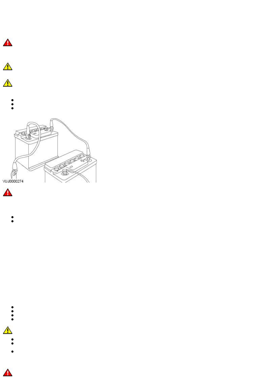
Always connect the jump leads in the following sequence.

Slave battery positive first then vehicle battery positive.
Slave battery negative next and then vehicle ground at least, 300 mm (12 in) from the battery terminal e.g. engine lifting bracket.

Always reduce the engine speed to idle before disconnecting the jump leads.

Before removing the jump leads from the vehicle that had the discharged battery, switch on the heater blower (high) or the heated rear
screen, to reduce the voltage peak when the leads are removed.

Always disconnect the jump leads in the reverse order to the connecting sequence and take great care not to short the ends of the leads.

Do not rely on the alternator to restore a discharged battery. For an alternator to recharge a battery, it would take in excess of 8 hours
continuous driving with no additional loads placed on the battery.

Component Cleaning

To prevent ingress of dirt, accumulations of loose dirt and greasy deposits should be removed before disconnecting or dismantling
components or assemblies.

Components should be thoroughly cleaned before inspection prior to reassembly.

Cleaning Methods:

Dry Cleaning
Removal of loose dirt with soft or wire brushes.
Scraping dirt off with a piece of metal or wood.
Wiping off with a rag.

CAUTION: Compressed air is sometimes wet so use with caution, especially on hydraulic systems.

Blowing dirt off with compressed air. (Eye protection should be worn when using this method).
Removal of dry dust using vacuum equipment. This method should always be used to remove friction lining material dust (asbestos
particles).
Steam Cleaning

Calibration of Essential Measuring Equipment

WARNING: Failure to comply may result in personal injury or damage to components.

It is of fundamental importance that certain essential equipment e.g. torque wrenches, multimeters, exhaust gas analysers, rolling roads
etc., are regularly calibrated in accordance with the manufacturers instructions.

Use of Control Modules

Control modules may only be used on the vehicle to which they were originally fitted. Do not attempt to use or test a control module on any
other vehicle.

Functional Test

On completion of a maintenance procedure, a thorough test should be carried out, to make sure that the relevant vehicle systems are
working correctly.

Preparation

Before disassembly, clean the surrounding area as thoroughly as possible. When components have been removed, blank off any exposed
openings using grease-proof paper and masking tape. Immediately seal fuel, oil and hydraulic lines when separated, using plastic caps or
plugs, to prevent loss of fluid and the entry of dirt. Close the open ends of oilways, exposed by component removal, with tapered hardwood
plugs or readily visible plastic plugs. Immediately a component is removed, place it in a suitable container; use a separate container for
each component and its associated parts. Before dismantling a component, clean it thoroughly with a recommended cleaning agent; check
that the agent will not damage any of the materials within the component. Clean the bench and obtain marking materials, labels,
containers and locking wire before dismantling a component.

Dismantling

Observe scrupulous cleanliness when dismantling components, particularly when parts of the brake, fuel or hydraulic systems are being
worked on. A particle of dirt or a fragment of cloth could cause a dangerous malfunction if trapped in these systems. Clean all tapped holes,
crevices, oilways and fluid passages with compressed air. Do not permit compressed air to enter an open wound. Always use eye protection
when using compressed air.

Make sure that any O-rings used for sealing are correctly refitted or renewed if disturbed. Mark mating parts to make sure that they are
replaced as dismantled. Whenever possible use marking materials which avoid the possibilities of causing distortion or the initiation of
cracks, which could occur if a center punch or scriber were used. W ire together mating parts where necessary to prevent accidental
interchange (e.g roller bearing components). Tie labels on to all parts to be renewed and to parts requiring further inspection before being
passed for reassembly. Place labelled parts and other parts for rebuild in separate containers. Do not discard a part which is due for renewal
until it has been compared with the new part, to make sure that the correct part has been obtained.

Inspection

Before inspecting a component for wear or performing a dimensional check, make sure that it is absolutely clean; a slight smear of grease
can conceal an incipient failure. W hen a component is to be checked dimensionally against figures quoted for it, use the correct equipment
(surface plates, micrometers, dial gauges etc.) in serviceable condition. The use of makeshift equipment can be dangerous. Reject a
component if its dimensions are outside the limits quoted, or if damage is apparent. A part may be refitted if its critical dimension is
exactly to the limit size and it is otherwise satisfactory. Use Plastigauge 12 Type PG-1 for checking bearing surface clearance, e.g. big end
bearing shell to crank journal. Instructions for the use of Plastigauge and a scale giving bearing clearances in steps of 0,0025 mm (0.0001
in) are supplied with the package.

On-Board Diagnostics (OBD)

This vehicle uses programmed electronic control systems to provide engine management and emission regulation, automatic transmission
operation and anti-lock braking control. These control systems are integral with the On-Board Diagnostics (OBD) facility which is used in
conjunction with either the Jaguar approved diagnostic system or the more restricted scan tools.

The OBD information in this manual provides diagnostic and rectification procedures for emission related electrical and mechanical systems.
The information is intended to facilitate fault diagnosis and the subsequent rectification of the vehicle without recourse to the Jaguar
approved diagnostic system.

The manual covers the following OBD topics:

General Information
Engine Management System
Automatic Transmission
Anti-lock Braking System

Each section comprises one or more of the following sub-sections as required.

The Description and Operation sub-section includes:

A general illustration and parts list to help the identification of the particular system or component.
A brief description of the system operating characteristics and monitoring procedure accompanied by a component illustration.
Additional information, where appropriate, is provided in the form of component calibrations, characteristics and cross sectional
views.
A localized circuit diagram is included to provide circuit identification, connectors, splices, fuses, wire gauge and colors. See Circuit
Diagrams.

The Diagnosis and Testing sub-section is dedicated to fault analysis and rectification, and includes:

Recommended special tools.
Symptom chart; a chart containing all relevant Diagnostic Trouble Codes (DTC), their possible causes and an indication of the
appropriate test.
Specific pinpoint test(s), designed so that fault diagnosis can be carried out in a logical and efficient manner.

The Removal and Installation sub-section covers:

Removal procedure(s), formatted in the recommended sequence.
Illustrated guide to the use of special tools.
Illustrations to support the relevant text.
Installation procedure as above and including special recommendations for processes, lubricants and tightening torques.

Circuit Diagrams

To understand the relationship between the vehicle electrical system and the system circuit diagrams, Refer to the Electrical Guide.

In the interest of clarity, single lines may represent multiple wires. Refer to the color code (1st alpha) followed by the wire reference
(numeric/alpha/numeric) to trace origin and destination.

e.g. BW 647B002. BW (black with white trace) 647 (wire reference) B002 (stage from origin).

Glossary of Terms

This glossary of terms is intended to cover mainly emissions-related (to SAE J 1930) terminology, and other abbreviations that may be used
in this manual.

The required term may be looked-up in the left-hand column, and subsequent columns give the standard acronym, unit or abbreviation, and
definition.

Term(s)

Acronym / Unit /

Abbreviation

Definition

Accelerator Pedal

AP

Accelerator Pedal Position
Sensor

APP

Is a multitrack sensor which inputs the drivers demand into the engine control module
(ECM)

After Bottom Dead Center

ABDC

Event occurring after BDC

After Top Dead Center

ATDC

Event occurring after TDC

Airbag / Supplementary
Restraint System

Airbag, SRS

Airbag restraint system for driver and front seat passenger

Air Cleaner

ACL

Air Conditioning

A/C

Air Conditioning Control
Module

A/CCM

Module controlling air conditioning, heating and ventilation

Air Conditioning Signal

ACS

Air conditioning compressor clutch operation is signalled to the ECM which induces idle
speed corrections to compensate for engine load changes

Alternating current

ac

Air Fuel Ratio

AFR

Nominally 14.7 parts air to one part fuel

Ampere

A

SI unit of current

Ampere hour

Ah

ABS Control Module

ABS CM

System which prevents wheel lock-up under braking by sensing lack of rotation of a
wheel(s) and diverting fluid pressure away from it (them)

ABS / Traction Control
Control Module

ABS/TCCM

System which prevents wheel lock-up under braking by sensing lack of rotation of a
wheel(s) and diverting fluid pressure away from it (them)

Atmosphere

atm

Unit of pressure (1.01325 bar)

Barometric Absolute
Pressure Sensor

BARO Sensor

Sensor measuring the pressure of surrounding air at any given temperature and altitude

Battery positive voltage

B+

The positive voltage from a battery or any circuit connected directly to it

Before Bottom Dead Center BBDC

Event occurring before BDC

Before Top Dead Center

BTDC

Event (usually ignition) occurring before TDC

Blower

BLR

Device which supplies a current of air at moderate pressure, e.g. heater or A/C blower

Body Processor Module

BPM

Control module for body electrical systems, e.g. interior lamps, windshield wash / wipe
control

Bottom Dead Center

BDC

Lowest point of piston travel in a reciprocating engine

Brake horsepower

BHP

Effective horsepower developed by an engine or motor, as measured by a brake applied to
its output shaft

Brake Mean Effective
Pressure

BMEP

The part of the effective pressure developed in a cylinder that would result in a cylinder
output equal to the bhp of the engine

Brake On/Off

BOO

Indicates the position of the brake pedal

British Standard

BS

Standard specification issued by the British Standards Institution

British Standard
Automotive

BSau

Bus

Topology of a
communication
network

Bypass Air

BPA

Mechanical control of throttle bypass air

Camshaft Position Sensor

CMP Sensor

Indicates camshaft position

Canadian Motor Vehicle
Safety Standard

CMVSS

Canister Purge

CANP

Controls purging of the EVAP canister

Carbon dioxide

CO2

Colorless gas with a density of approximately 1.5 times that of air

Carbon monoxide

CO

Poisonous gas produced as the result of incomplete combustion

Case Ground

CSE GND

Control module casing ground

Catalytic converter

In-line exhaust system device used to reduce the level of engine exhaust emissions

Celsius

C

SI term for the Centigrade scale, with freezing point at zero and boiling point at 100
degrees

Central Processor Unit

CPU

The section of a computer that contains the arithmetic, logic and control circuits. It
performs arithmetic operations, controls instruction processing, and provides timing
signals and other housekeeping operations

Cylinder Head Temperature
Sensor

CHT Sensor

A sensor for measuring the temperature of the cylinder head

Closed Loop

CL

Closed Loop System

CL System

Control system with one or more feedback loops

Column/Mirror Control
Module

C/MCM

A self-contained group of electrical /electronic components, designed as a single
replaceable unit, and controlling one or more processes

Controller Area Network

CAN

A communication system which allows control modules to be linked together.

Crankshaft Position Sensor CKP Sensor

Generates crankshaft position information in conjunction with the CKPTR (also generates
speed information in certain applications)

Crankcase Ventilation
System

CV

System which scavenges camshaft cover and crankcase emissions and feeds them into the
inlet manifold

Cubic centimeter

cm³

Curb weight

Weight of vehicle with fuel, lubricants and coolant, but excluding driver, passengers or
payload

Data Link Connector

DLC

Connector providing access and/or control of the vehicle information, operating conditions,
and diagnostic information

Term(s)

Acronym / Unit /

Abbreviation

Definition

Data Output Line

DOL

Circuit that sends certain information from the ECM to the instrument cluster

Degree

deg, °

Angle or temperature

Department of
Transportation (US)

DOT

Which is a fibre optic ring network, can be diagnosed through the SCP network, and with
the optical bus tester.

Deutsche Institut fur
Normung

DIN

German standards regulation body

Diagnostic Module

DM

Supplemental Restraint System (non -controlling) module for diagnostics overview

Diagnostic Test Mode

DTM

A level of capability in an OBD system. May include different functional states to observe
signals, a base level to read DTCs, a monitor level which includes information on signal
levels, bi-directional control with on/off board aids, and the ability to interface with
remote diagnosis

Diagnostic Trouble Code

DTC

An alpha/numeric identifier for a fault condition identified by the On-Board Diagnostic
(OBD) system

Differential pressure

Pressure difference between two regions e.g. between intake manifold and atmospheric
pressures

Differential Pressure
Feedback EGR

DPFE

An EGR system that monitors differential EGR pressure across a remote orifice to control
EGR flow

Direct current

dc

Current which flows in one direction only, though it may have appreciable pulsations in its
magnitude

Domestic Data Bus

D2B

Exhaust Gas Recirculation
Temperature Sensor

EGRT

Sensing EGR function based on temperature change

Engine Management
System

EMS

The engine management system conditions and reads inputs, supplies processing
capability, and provides output drivers to control actuators as directed by software and
calibration

Engine Oil Pressure

EOP

EGR Vacuum Regulator

EVR

Controls EGR flow by changing vacuum to the EGR valve

EGR Valve Position

EVP

An EGR system that directly monitors EGR valve position to control EGR flow

Electrically Erasable
Programmable Read-Only
Memory

EEPROM

Electrically Programmable
Read-Only memory

EPROM

Electronic Secondary Air
Injection

EAIR

A pump-driven system for providing secondary air using an electric air pump

Engine Control Module

ECM

Engine Coolant Level

ECL

Engine Coolant
Temperature

ECT

ECT Sensor

ECTS

Thermistor which provides engine coolant temperature signal to the ECM to trigger
enrichment circuits which increase injector 'on' time for cold start and warm-up

Engine speed

RPM

Environmental Protection
Agency

EPA

Evaporative Emission

EVAP

System designed to prevent fuel vapor from escaping into the atmosphere. Typically
includes a charcoal filled canister to absorb fuel vapor

Evaporative Emission
Control Valve

EVAPP

Exhaust Gas Recirculation

EGR

System which reduces NOx emissions by adding exhaust gases to the incoming fuel/air
charge

Exhaust Gas Recirculation
Solenoid Vacuum Valve

EGRS

Exhaust Gas Recirculation
Temperature Sensor

EGRT Sensor

Exhaust Gas Recirculation
Valve

EGR Valve

Fan Control

FC

Engine cooling fan control

Federal Motor Vehicle
Safety Standard (US)

FMVSS

Figure

Fig.

Illustration reference

Flash Electrically Erasable
Programmable Read-Only
Memory

FEEPROM

Flash Erasable
Programmable Read-Only
Memory

FEPROM

Flywheel Sensor

CKFS

Sensor mounted so as to be triggered by each flywheel ring gear tooth to give an engine
speed signal

Fuel Injection

FI

Solenoid operated devices that spray a metered quantity of fuel into the inlet ports

Fuel Pressure Regulator
Control

FPRC

Controls fuel pressure regulator; used primarily to give extra fuel at cold start-up

Fuel Pump

FP

Pumps fuel from the fuel tank to the fuel injection system

Fuel Pump Monitor

FP Module

Monitors operation of fuel pump

Fuel Pump Relay

FP Relay

Relay which controls electrical current to fuel pump

Fuel rich/lean

Qualitative evaluation of air/fuel ratio based on a ratio known as stoichiometry,or 14.7:1
(Lambda)

Generic Electronic Module

GEM

Generator

GEN

Rotating machine which converts mechanical energy into electrical energy

Gramme centimeter

gcm

Gramme (force)

gf

Gramme (mass)

g

Ground

GND

Electrical conductor used as a common return for an electrical circuit or circuits, and with a
relative zero potential

Hard fault

A fault currently present in the system

Headlamp

HL


Content   ..  11  12  13  14   ..