JAC S2 (Chassis). Service Manual - part 13


  Index      JAC     JAC S2 (Chassis). Service Manual


Search            copyright infringement  


Content      ..     11      12      13     


JAC S2 (Chassis). Service Manual - part 13


Brake Control System


Brake Control System 


         182 

(II) Installation 

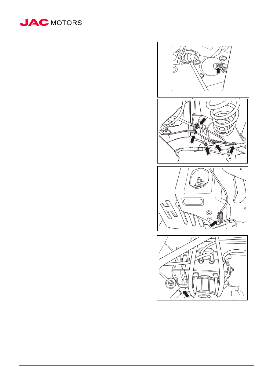
1. Install the rear wheels’ ABS speed sensor assembly 

1). Install the fixing bolt that fixes rear wheels’ speed 
sensor 

Tightening torque 8~10N.m 
△Notice   

1. Do not drag the sensor’s harness brutely 

2. Mind the gap between speed sensor and signal’s gear 

ring 

Standard: 0.2~1.1mm 


2). Install the fixing point that connects sensor’s 
harness and vehicle body, and the three fixing points 
that connect with rear torsion beam 


3). Connect the harness connector of front wheels’ 
speed sensor 

2. Install the front wheels’ hub 
3. Install the railgate’s side panel 
4. Install the reargate’s threshold cover 
5. Install the tailgate’s threshold cover 
6. Install the rear seat’s rotating bracket 
7. Install the C column’s trim and decorated 

8. Install the rear seat’s backrest 
9. Install the rear seat’s cushion 
10. Install the rear wheels 
11. Connect the negative cable of battery 
12. Close the engine hood 


-------------------------------------------------------------------------------------------------------------------------------------------------------------


Brake Control System


Brake Control System 


         183 


VII ESP controller assembly 

(I) Disassembly 

1. Open the engine hood 
2. Disconnect the negative cable of battery 
3. Drain the brake fluid, please refer to “brake fluid” 
4. Dismantle ESP controller assembly 

1). Disconnect the harness connector of ESP controller 
assembly 


2). Disassemble the oil outlet tube assembly in master 
cylinder, front brake pipeline assembly and right-front 
brake oil pipe assembly, which are connected to ESP 
controller assembly 


3). Dismantle the ESP controller’s support and the three 
fixing nuts that fix the support 

4). Take out the ESP controller 


(II) Installation 

1. Install the ESP controller 

1). Install the three fixing nuts that connect ESP 
controller and the support 


-------------------------------------------------------------------------------------------------------------------------------------------------------------


Brake Control System


Brake Control System 


         184 

2). Install the oil outlet tube assembly in master cylinder, 
front brake pipeline assembly and right-front brake oil 
pipe assembly, which are connected to ESP controller 
assembly 

Tightening torque 16~18N.m 


3). Connect the harness connector of ESP controller 
assembly 

2. Add brake fluid, please refer to “brake fluid” 
3. Exhaust air from brake system, please refer to “air-removal of brake system” 
4. Connect the negative cable of battery 
5. Close the engine hood

-------------------------------------------------------------------------------------------------------------------------------------------------------------


EPS (Electronic Power Steering)


EPS (Electronic Power Steering) 


          185 


EPS  (Electronic Power Steering) 

I Brief introduction 

(I) Structural introduction 

EPS’s structural diagram 


1. Steering wheel assembly                            3. Steering shaft with universal shaft 
2. Steering column assembly                           4. Steering gear assembly 


-------------------------------------------------------------------------------------------------------------------------------------------------------------


EPS (Electronic Power Steering)


EPS (Electronic Power Steering) 


          186 

(II) System’s working principle 

Diagram of system’s working principle 


(III) Maintenance parameter 

Project 

Standard 

Type of manual steering gear 

Gear rack 

Parameter of steering wheel 

φ375mm 

Steering column and lower shaft 

Crumple level 3 

Operating torque of steering wheel 

≤ 5N·m 

Power steering gear rack’s travel distance 

134±1mm 

Cord’s transmission ratio 

46.82 

Steering wheel’s number of turns 

2.86±0.04 


-------------------------------------------------------------------------------------------------------------------------------------------------------------


EPS (Electronic Power Steering)


EPS (Electronic Power Steering) 


          187 

 (IV) Torque parameter 

No. Project 

Torque
(N·m) 

Remark 

1  Steering wheel’s fixing nut 

42~52 


2  Steering column’s installing nut 

20~25 


3  Steering column’s installing bolt 

20~30 


4  Controller support’s fixing bolt 

8~10 


5  Connecting bolt of steering column assembly and steering shaft 

assembly 

30~35 


6  Connecting bolt of steering shaft assembly and manual steering gear   30~35 


7  Primary fixing bolt of manual steering gear 

95~105 


8  Secondary fixing bolt of manual steering gear 

95~105 


9  Toe-in adjusting nut of steering tie rod 

45~55 


10  Slotted nut of steering gear’s external ball 

40~50 


(V) Maintenance precautions 


1. When checking steering system, park the car on dry and level ground 
2. All bolts of spare parts in steering system must be tightened with standard torque 
3. Check the wheel alignment after finishing the maintenance of steering column assembly, steering 
gear and other steering part. 
4. The system’s voltage standard is 9~18V. 
5. Check the tire’s pressure often and make sure it meets the standard. 
6. Once abnormal gap or front-sway appears, confirm which system or assembly the problem exists in, 
and solve the problem. 
7. Check whether the spare parts of steering system suffer abnormal crash, and replace the broken or 
problematic parts immediately 
8. It is unacceptable to weld any part of steering gear or system rod piece. 
9. Check regularly whether any interference or abrasion is on EPS harness, or whether the connector is 
loosen, and replace harness if necessary. 

II Failure diagnosis 

(I) Chart of diagnostic trouble codes for EPS 

No. DTC 

Description 

1  C1611  Failure happens in torque sensor’s main signal 

2  C1613  The difference between primary and secondary circuit of 

torque sensor is excessive 

3  C1614  Torque sensor’s power failure 

4  C1615  Failure of signal in torque sensor’s secondary circuit 

5  C1621  Vehicle speed’s signal loss 

6  C1622  Wheel speed’s signal loss 

7  C1624  Vehicle speed’s reduction exceeds normal level 

8  C1641  Motor’s circuit is open or I short-out; drive circuit is 

abnormal 

9  C1642  Motor’s practical current is far higher than estimated 

current 

-------------------------------------------------------------------------------------------------------------------------------------------------------------


EPS (Electronic Power Steering)


EPS (Electronic Power Steering) 


          188 

10  C1643  Motor’s current is too excessive 

11  C1645  Motor’s practical current is far lower than estimated current 

12  C1651  Angle transducer’s signal is abnormal 

13  C1652  Controller’s relay fails 

14  C1653  Power voltage is too low 

15  C1654  Power voltage is too high 

16  C1655  Drive failure (over-temperature, undervoltage) 

17  U0073  EPS communication is down 

18  U0100  Loss of communication with EMS/ECU 

19  U0129  Loss of communication with ABS/BSM 

20  C1611  Torque sensor-primary signal’s cross-border 

21  C1612  Torque sensor-secondary signal’s cross-border 

22  C1613  Torque sensor-sum of primary and secondary signal brakes 

limit 

23  C1614  Torque sensor-torque sampling overtime 

24  C1661  Relay’s circuit is open 

25  C1621  Battery’s voltage is too high 

26  C1622  Battery’s voltage is too low 

27  C1662  Current sensor-mid-current’s calibration error 

28  C1663  Current sensor-excessive current 

29  C1664  +5VA voltage error 

30  C1632  EEPROM data consistency failure 

31  C1643  Ignition signal loss 

32  C1651  Motor-circuit’s short-out 

33  C1667  Temperature sensor-MOSFET overheat 

34  C1615  Angle sensor-PWM’s duty-ratio exceeds the limit  

35  C1617  Angle sensor-angle’s calculation error 

36  C1615  Angle sensor-PWM frequency is abnormal 

37  C1616  Angle sensor-P or S signal sampling overtime 

38  C1641  CAN- invalid vehicle speed 

39  C1641  CAN- vehicle speed sampling is overtime 

40  C1642  CAN- invalid wheel speed 

41  C1642  CAN- wheel speed sampling is overtime 

42  U1000  CAN-BUSOFF 

-------------------------------------------------------------------------------------------------------------------------------------------------------------


EPS (Electronic Power Steering)


EPS (Electronic Power Steering) 


          189 

43  U1000  CAN-message transmission overtime 

44  C1665  EPS controller-inside failure 

(II) Failure diagnosis 

No. Symptom 

Failure’s reason 

Solution 

Remark 

1  Vehicle’s deviation 

Steering wheel’s ball joint 
is loosen or the front 
wheel’s alignment is 
inappropriate 

Adjust the alignment 
and ball joint in steering 
wheel 

Please refer 
to ”vehicle’s 
steering system 
check” 

Steering lever system is 
broken or suffer excessive 
abrasion 

Check and adjust each 
joint part in steering 
system according to the 
instructions 

Rack’s pre-tightening 
degree is in maladjustment. 

Adjust or repair the 
rack’s pre-tightening 
degree in the steering 
gear 

Power-steering is 
sporadic or back to 
normal after 
restarting the engine. 

Harness connector is loosen 
or in poor contact 

Check and reconnect the 
connectors, make sure 
they are connected 
firmly 

Please refer 
to ”vehicle’s 
steering system 
check” 

Motor’s fuse is loosen or in 
poor contact 

Re-install the fuse, make 
sure it is installed 
properly 

Motor’s failure 

Replace the motor 

EPS controller’s failure 

Replace the EPS 
controller 


-------------------------------------------------------------------------------------------------------------------------------------------------------------


EPS (Electronic Power Steering)


EPS (Electronic Power Steering) 


          190 

(III) Diagnostic flow chart 

Flow chart of combination instrument’s EPS warning light keeps lighting, no steering function 


-------------------------------------------------------------------------------------------------------------------------------------------------------------


EPS (Electronic Power Steering)


EPS (Electronic Power Steering) 


          191 

III Vehicle’s steering system check 

(I) Check 

1. Check the installation 

1). Check the installing situation of steering gear assembly, front suspension, axle and steering 
column 

2). Check whether there is any gap during axial movement 

3). Check whether the fixing nuts and bolts of steering gear assembly are loosen 

2. Check the free-running distance of steering wheel 

1). Turn the steering wheel and keep the front wheels straight ahead. Start the engine, and slightly 
turn the wheel left or right, tillthe front wheel starts to move, and measure the steering wheel’s 
distance on the excircle  

Steering wheel’s free-running distance: 30mm 

2). If the measured value exceeds the standard, check the installing situation of all joints of steering 
column and the steering assembly, and adjust or replace relevant spare parts if necessary.  

3). If the free-running distance still exceeds 30mm, then shut down the engine and keep the front 
wheels straight ahead. Apply a force of 5N along the steering wheel’s periphery and check the free-
running distance. If the distance exceeds 10mm, then it is necessary to check whether the steering 
assembly is qualified.  

4). If the distance still stays at limit, then keep the wheel straight when the engine is dead, apply a 
force of  4±0.6N along the wheel’s periphery, and check the free-running distance.  

Standard: <15mm 

5). If the distance above exceeds the standard, then disassemble the steering gear and check pinion’s 
total torque. 

3. Check the middle position 

1). Confirm whether steering gear assembly, column and 
wheel are installed correctly. 

2). Carry out middle position check after the front 
wheels’ alignment. Please refer to “front wheels’ 
alignment” 

3). Park the vehicle directly, and confirm the steering 
wheel is in the middle position. 

4). Loosen the locknut of tie rod and turn the adjustment 
lever slightly, and confirm whether the steering wheel 
still stays at middle position. 

4. Check the steering wheel’s static steering force 

1). Park the vehicle on dry and level ground, and pull up the brake handle. 

2). Start the engine. 
△Notice  the tire’s pressure should stays in limit 

3). Turn the steering wheel a circle from middle position, check the wheel’s steering force, and 
whether any apparent fluctuation exists. 

steering wheel’s steering force:  <34N 

acceptable fluctuation: <5.9N 

-------------------------------------------------------------------------------------------------------------------------------------------------------------


EPS (Electronic Power Steering)


EPS (Electronic Power Steering) 


          192 

4). If the steering force exceeds the limit, please check or adjust the following parts: 

(1). Check whether the lower suspension arm or steering tie rod’s ball joint is broken 

(2). Check the steering gear’s preload and the driving torque of steering tie rod  

(3). Check the driving torque of lower suspension arm’s ball joint 

5. Check the steering wheel’s self-return 

1). Turn the steering wheel for 90°, and drive the vehicle in 35km/h. Keep the speed for several 
seconds, and loosen the steering wheel. The auto-return should be at least 70%. 
△Notice  During slow or sharp turn, check whether the 
auto-return in left and right direction is same, by using 
personal feeling. This check must be carried out on safe 
roads, and keep personal safety as priority 

6. Check the front wheels’ steering angle 

1). After the toe-in check of front wheel, carry out 
steering angle check. When the vehicle is still, and 
engine is in idle speed, place the front wheel on steering 
angle measurer, and check the maximum steering angle 
of inner and external wheels. 

Inner wheel: 35.1°±1.5°  

External wheel: 30.6°±1.5° 
△Notice  if the measured value is not in the limit, adjust 
the tie rod 

7. Steering angle’s adjusting method 

1). When the steering angle exceeds the limit, loosen the locknut of left and right steering tie rod, and 
use wrench to adjust the tie rod till the angle meets the standard. Then tighten the locknut, and the 
tightening torque is 45~55N.m. When re-adjust left and right tie rod, keep the left rod and right rod 
equal 
△Notice  if the inner wheel’s steering angle exceeds limit, adjusting the tie rod to the outside will 
increase inner wheel’s angle; when external wheel’s steering angle exceeds limit, adjusting the tie rod 
to the outside will reduce external wheel’s angle. The vehicle’s toe-in is relevant to the adjustment of 
other four wheels’ alignment and steering angle. 

8. Check the dust cover of ball joint 

1). Press the cover by fingers to check whether the dust cover is chap or broken 

2). If any chap or  damage exists on dust cover, replace the tie rod’s ball joint immediately. 
△Notice  dust cover’s chap or damage on surface may also cause ball joint to suffer damage. 

9. Check the tie rod’s ball joint 

1). Quickly sway the tie rod for 10 times 

2). Use spring scale to measure the swinging resistance of tie rod 

Standard: 0.5~3N.m. If the measured value exceeds the limit range, replace tie rod immediately. 


IV Steering wheel assembly 

(I) Disassembly 

1. Open the engine hood 

-------------------------------------------------------------------------------------------------------------------------------------------------------------


EPS (Electronic Power Steering)


EPS (Electronic Power Steering) 


          193 

2. Disconnect the negative cable of battery 
△Notice 


wait for at least 3 minutes after disconnecting the cable, in case of air bag’s explosion during 
disassembly 
3. Dismantle driver’s air bag assembly, please refer to 
“driver’s air bag assembly” 
4. Disassemble the steering wheel assembly 

1). Turn the steering wheel, and make sure the front 
wheels are on straight line 

2). Lock the steering wheel 
△Notice  make marks before pulling out steering wheel, 
and make sure the steering wheel’s position after 
installation is the same as the one before. 


3). Loosen the fixing nut of steering wheel 

4). Pull out the steering wheel from steering shaft 
△Notice  pre-tighrten the fixing nut to steering wheel, 
in case of injuring maintenance personnel when pulling 
out the steering wheel 
△Notice  if the steering wheel cannot be pulled out 
manually, it is OK to use professional tools 


(II) Installation 

1. Install the steering wheel assembly 

1). Turn the clock spring clockwise till the stop position, 
and turn it 3 circles counter-clockwise 

2). Engage the steering wheel to the spline of steering 
column 
△Notice  the locking slot, which is in the bottom of 
steering wheel, must match the locating pin of spiral 
cable 

3). Install the fixing nut and washers 

Tightening torque: 42~52N.m 

4). Adjust the steering wheel’s steering angle to 0 
△Notice  after the dismounting of steering column, the wheel’s steering angle may be affected, 
while the pilot lamp on dashboard hasn’t lighted. It is necessary to carry out steering wheel’s signal 
calibration. After calibration, when the ignition switch is in “ON” position, EPS controller will 
inspect each module of the system, and light the EPS pilot lamp. If self-inspection is normal, the pilot 
lamp will die in 2 seconds. 

2. Install driver’s air bag assembly 

3. Connect the negative cable of battery 

4. Close the engine hood 

-------------------------------------------------------------------------------------------------------------------------------------------------------------


EPS (Electronic Power Steering)


EPS (Electronic Power Steering) 


          194 


V Steering column assembly 

(I) Disassembly 

1. Open the engine hood 
2. Disconnect the negative cable of battery  

△Notice  wait for at least 3 minutes after disconnecting 
the cable, in case of air bag’s explosion during 
disassembly 

3. Dismantle driver’s air bag assembly, please refer to “driver’s air bag assembly” 
4. Disassemble the steering wheel assembly, please refer to “steering wheel assembly” 
5. Disassemble the cladding of steering column, please refer to “cladding of steering column” 
6. Disassemble the clock spring, please refer to “clock spring” 
7. Dismantle the combination switch, please refer to “combination switch” 
8. Dismantle the driver side’s back-plate, please refer to “driver side’s back-plate” 
9. Disassemble the guard induction coil, please refer to “guard induction coil” 
10. Dismantle the ignition lock assembly, please refer to 
“ignition lock assembly” 
11. Disassemble the steering column assembly 

1). Disconnect the harness connector on steering column 


2). Unfix the harness on steering column 

3). Loosen the fixing bolt that connects the lower end of 
steering column assembly and dashboard skeleton 

4). Loosen the two fixing bolts that connect the upper 
end of steering column and dashboard skeleton 


5). Loosen the fixing bolt that connects steering column 
assembly and steering shaft assembly with universl shaft 

6). Take off the steering column assembly 


-------------------------------------------------------------------------------------------------------------------------------------------------------------


EPS (Electronic Power Steering)


EPS (Electronic Power Steering) 


          195 

(II) Installation 

1. Install the steering column assembly 

1). Install the fixing bolt that connects the lower end of 
steering column assembly and dashboard skeleton 

Tightening torque 20~30N.m 

2). Install the two fixing bolts that connect the upper end 
of steering column assembly and dashboard skeleton 

Tightening torque 20~25N.m 

VI Steering shaft assembly with universal shaft 

(I) Disassembly 

1. Open the engine hood  
2. Disconnect the negative cable of battery  

△Notice  wait for at least 3 minutes after disconnecting 
the cable, in case of air bag’s explosion during 
disassembly 

3. Dismantle driver’s air bag assembly, please refer to “driver’s air bag assembly” 
4. Disassemble the steering wheel assembly, please refer to “steering wheel assembly” 
5. Disassemble the cladding of steering column, please refer to “cladding of steering column” 
6. Disassemble the clock spring, please refer to “clock spring” 
7. Dismantle the combination switch, please refer to “combination switch” 
8. Dismantle the driver side’s back-plate, please refer to “driver side’s back-plate” 
9. Disassemble the guard induction coil, please refer to “guard induction coil” 
10. Dismantle the ignition lock assembly, please refer to “ignition lock assembly” 
11. Disassemble the steering shaft assembly with universal shaft 

1). Loosen the fixing bolt that connects steering column 
and steering shaft 


2). Loosen the fixing bolt that connects steering shaft 
and steering gear 

3). Take off the steering shaft assembly with universal 
joint 


-------------------------------------------------------------------------------------------------------------------------------------------------------------


EPS (Electronic Power Steering)


EPS (Electronic Power Steering) 


          196 

(II) Installation 

1. Install the steering shaft assembly with universal joint 

1). Tighten the fixing bolt that connects steering shaft 
and steering gear 

Tightening torque 30~35N.m 


2). Tighten the fixing bolt that connects steering column 
assembly and steering shaft assembly  

Tightening torque: 30~35N.m 

3). Adjust the steering wheel’s steering angle to 0 
△Notice  after the dismounting of steering column, the 
wheel’s steering angle may be affected, while the pilot 
lamp on dashboard hasn’t lighted. It is necessary to carry 
out steering wheel’s signal calibration. After calibration, 
when the ignition switch is in “ON” position, EPS 
controller will inspect each module of the system, and 
light the EPS pilot lamp. If self-inspection is normal, the 
pilot lamp will die in 2 seconds. 

2. Install the guard induction coil 
3. Install the driver-side back-plate 
4. Install the combination switch 
5. Install the clock spring 
6. Install the steering wheel assembly  
7. Install the cladding of steering column  
8. Install the driver’s air bag assembly  
9. Connect the negative cable of battery  
10. Close the engine hood 


VII Steering gear assembly 

(I) Disassembly 

1. Disassemble the left-front wheel, please refer to “wheels” 
2. Disassemble the right-front wheel, please refer to 
“wheels” 
3. Dismantle left-lower suspension arm assembly, please 
refer to “lower suspension arm”  
4. Dismantle right-lower suspension arm assembly, please 
refer to “lower suspension arm” 
5. Dismantle the front sub-frame assembly with stabilizer 
bar and steering gear, please refer to “front sub-frame 

-------------------------------------------------------------------------------------------------------------------------------------------------------------


EPS (Electronic Power Steering)


EPS (Electronic Power Steering) 


          197 

assembly” 
6. Disassemble the steering gear assembly 

1). Disassemble the two hex flange-face nuts and two 
gear locknuts that connect gear assembly and front 
subframe 

2). Take off the steering gear assembly 


(II) Installation 


1. Install the steering gear assembly 

1). Put the gear assembly on the installing position of front 
sub-frame  

2). Install the two hex flange-face nuts and two gear 
locknuts that connect gear assembly and front sub-frame 

Tightening torque 95~105N.m 

3). Adjust the tie rod’s left and right length according to 
the value before maintenance, and tighten the locknut 
after the adjustment. 

Tightening torque 45~55N.m 

4). Adjust the steering wheel’s steering angle to 0 
△Notice  after the dismounting of steering column, the 
wheel’s steering angle may be affected, while the pilot 
lamp on dashboard hasn’t lighted. It is necessary to carry 
out steering wheel’s signal calibration. After calibration, 
when the ignition switch is in “ON” position, EPS 
controller will inspect each module of the system, and 
light the EPS pilot lamp. If self-inspection is normal, the 
pilot lamp will die in 2 seconds. 

2. Install the front sub-frame assembly with stabilizer bar and steering gear  
3. Install the right lower suspension arm assembly 
4. Install the left lower suspension arm assembly  
5. Install the right-front wheel  
6. Install the left-front wheel
 

-------------------------------------------------------------------------------------------------------------------------------------------------------------


Content      ..     11      12      13