JAC S2 (Chassis). Service Manual - part 9
Wheel and Tire
Wheel and Tire
118
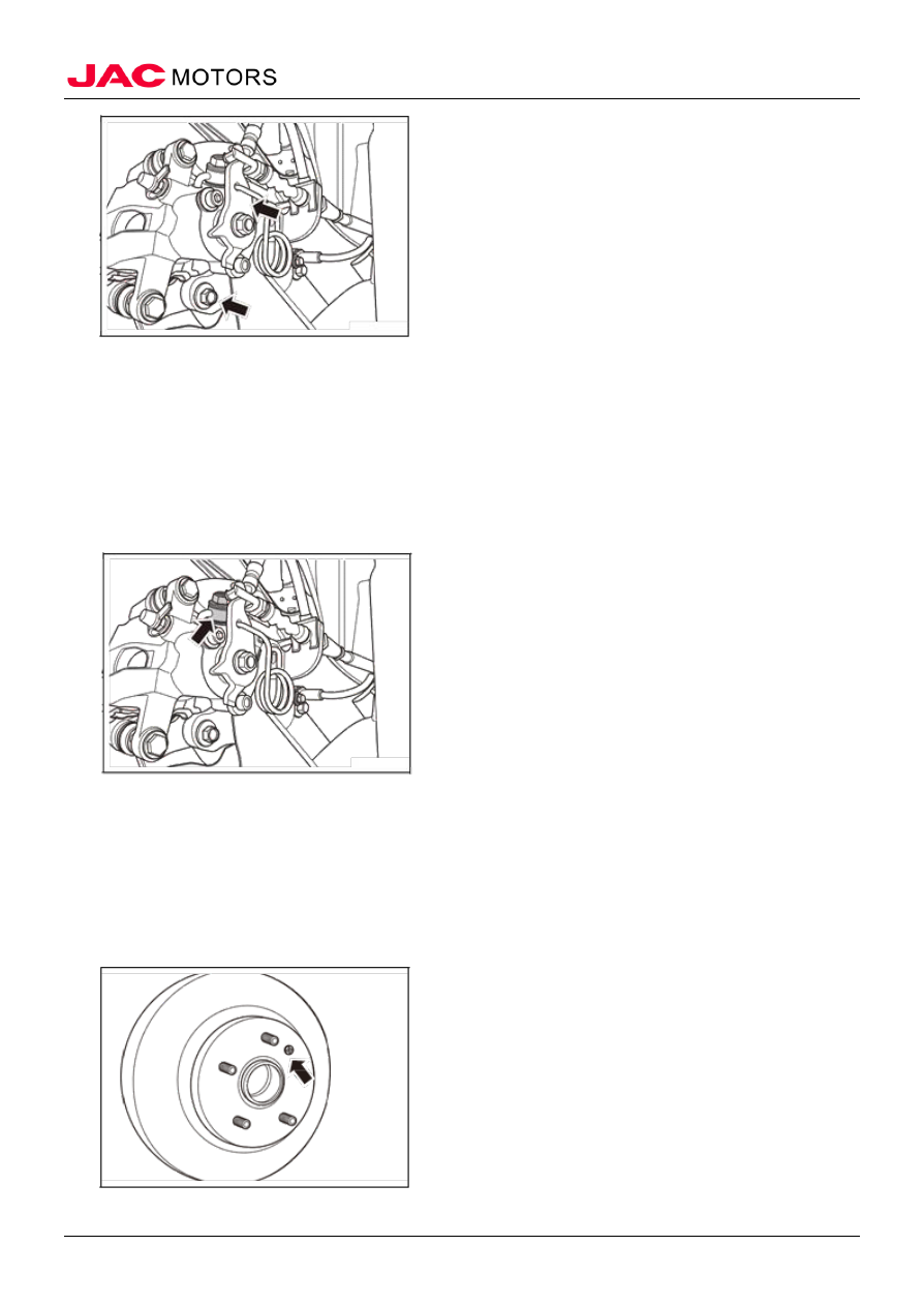
3) Install brake hose bolts and copper washers connecting
the rear brake hose and brake pad.
Tightening torque 25 ~ 30N • m
4) Install rear brake caliper assembly and rear parking
brake drawing connections.
2. Fill brake fluid refers to brake fluid.
3. Drain brake system exhaust refers to brake system exhaust.
4. Install the wheel
VIII Rear brake disc
(I) Remove
1. Remove the wheels refers to wheels
2. Remove the rear brake caliper assembly refers to the rear brake caliper assembly
3. Remove the rear brake disc
1). Remove the brake disc rear cross screws.
2). Remove the brake disc
(II) Check