JAC S2 (Chassis). Service Manual - part 7


  Index      JAC     JAC S2 (Chassis). Service Manual


Search            copyright infringement  


Content      ..     5      6      7      8     ..


JAC S2 (Chassis). Service Manual - part 7


Rear suspension


Rear suspension   


            86 

9). Install the fixing point connecting the rear brake 
discharge pipe assembly and the torsion beam assembly. 

2. Install the left rear brake pipe assembly, the right rear brake pipe assembly.


3. Install the left rear caliper assembly 
4. Install the right rear brake caliper assembly 
5. Install the right rear wheel 
6. Install the left rear wheel 
7. Fill the brake fluid refers to brake fluid 
8. Drain brake System refers to brake system 
9. Connect the negative battery cable 
10. Close the engine hatch 


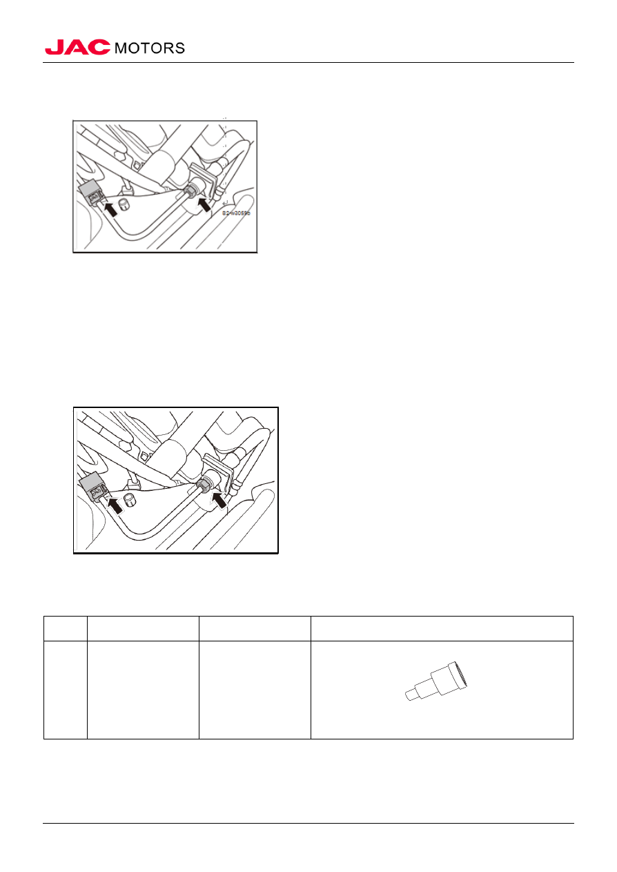
VI. Rear wheel hub assembly 

(I) Special tools 
 

No 

Tool No 

Tool name 

Outlook 


Hub Installation 
Tools 


(II) Remove 


1. Remove the wheels refers to the wheels 
2. Drain the brake fluid refers to the brake fluid. 
3. Remove the rear brake caliper assembly refers to the rear brake caliper assembly 

-------------------------------------------------------------------------------------------------------------------------------------------------------------


Rear suspension


Rear suspension   


            87 

4. Remove the brake disc assembly refers to the rear brake discs 
5. Remove the rear wheel hub assembly 

1). Remove a fixing bolt connecting the rear ABS wheel 
speed sensor and rear hub assembly. 

2). Disengage the connection between the rear ABS wheel 
speed sensor and the rear wheel hub assembly. 


3) Remove four fixing bolts connecting the rear torsion 
beam assembly and hub assembly. 


4) Remove the rear wheel hub assembly. 

(III) Installation 

1. Install the rear wheel hub assembly 

1).Successively connects the rear brake disc, rear brake 
fender, and the rear wheel hub assembly to the torsion 
beam. 

2) Install four mounting bolts from inside the torsion beam 
assembly connecting the rear hub assembly and the 
torsion beam. 
Tightening torque 60 ~ 72N • m 

-------------------------------------------------------------------------------------------------------------------------------------------------------------


Rear suspension


Rear suspension   


            88 


3) Install a fixing bolt connecting the rear ABS wheel 
speed sensor and rear hub assembly. 
Tightening torque 8 ~ 10N • m 


2. Install the rear brake disc assembly 
3. Install the rear brake caliper assembly 
4. Fill the brake fluid refers to brake fluid 
5. Drain the brake system refers to brake system 
6. Install the rear wheel 


-------------------------------------------------------------------------------------------------------------------------------------------------------------


 Wheel and Tire


Wheel and Tire   


            89 

Wheel and Tire 

I Overview 

(I) Structure summary 

Tire structure (steel) 


1. Tire (205/55 R16) 
2. TR414 valve 
3. Balancing Pad 
4. Steel rim (6.5Jx16) 
5. Tire nut 
6. The wheel cap 


-------------------------------------------------------------------------------------------------------------------------------------------------------------


 Wheel and Tire


Wheel and Tire   


            90 


Tire structure (aluminum wheels) 


1. Aluminum rims (6.5Jx16) 
2. The tire (205 / 55R16) 
3. The tire pressure sensors 
4. The decorative cover assembly 
5. Wheel Nut 
6. The tire pressure label 


-------------------------------------------------------------------------------------------------------------------------------------------------------------


 Wheel and Tire


Wheel and Tire   


            91 

 Spare tire structure 


1. Tires 
2. The balance weight 
3. Rim 
4. The spare tire fixing stud assembly 
5. Valve 


-------------------------------------------------------------------------------------------------------------------------------------------------------------


 Wheel and Tire


Wheel and Tire   


            92 

Tire pressure 

Tire pressure has a decisive influence on the aspects of tire wear, fuel consumption, fault damage, 

therefore, in order to drive safely, maintain standard pressure and check the tire pressure regularly. 

The load capacity of the tire is corresponding to inflation pressure; determine a reasonable tire 

pressure according to the condition of the vehicle load capacity. Climate and season changes should not 
be a reason to adjust the tire pressure. 

Incorrect tire pressure can cause: 

1) Tires with no enough pressure will cause tire shoulder 
quicker wear, tire deflection, rolling resistance increasing 


2).  Excessive tire pressure causes rapid wear of the 
middle part of the tire tread, and reduce tire buffer 
capacity. 

Tire transposition  

When running the wear situation of the front and rear wheels of the vehicle will be very different 

according to the different load capacity, so in order to avoid tire wear by a single direction, regular and 
timely transposition to make tires wear evenly, thereby extending the life of the tire. 

NOTE: tire should be transposed when reach 8000km. 

Tires should be transposed if new tires are replaced. 

1) The recommended tire transposition 


Wheel replacement 

1. The wheel should be replaced when reaches 50000km in normal driving. 
2. If one of the following occurs, it needs to be replaced: 

1).The tire tread has worn at least three markers. 

2) Tire rubber cords or cords appear. 

-------------------------------------------------------------------------------------------------------------------------------------------------------------


 Wheel and Tire


Wheel and Tire   


            93 

3) The tire tread or tire shoulder crack and cords occur. 

4) Tire bump, bulge or delamination. 

5) Tire punctured, scratched or otherwise damaged, its 
extent is difficult to repair. 


Wheel alignment 

Correct wheel alignment plays an important role for stable good control of the vehicle, eliminating the 
abnormal tire wear, reducing driver fatigue.  
Wheel alignment parameters include: 

1. Toe 

Toe is the difference between the distance of the two front wheels and the distance of the same 

wheels two rear ends. If the wheels are perfectly parallel and the toe is zero. If the front wheel inwardly 
inclined to car center line, the toe angle is positive. Otherwise the toe is negative. 

The function of the toe is compensating the inward or outward rolling tendency caused by camber 

angle of the tire and the road surface resistance. 


2. Camber 

Camber is tire relative angle to the vertical reference line, when the top of a wheel tilts outward, 

portion is defined as positive, otherwise defined as negative. Camber settings can affect the control of 
the vehicle direction and tire wear. 

Improper camber settings can cause excessive tire wear or uneven wear, too much positive 

camber will cause the outer tire tread wear, when the load of the outside tread is higher than the inner 
side, it will cause uneven wear. 

Excessive negative camber will cause the inside of the tire tread wear, the load of the inside tread 

is higher than the outside, it will cause uneven wear. 


3. Caster  

Caster angle is the vertical angle between the kingpin axis and the ground. Kingpin caster angle 

-------------------------------------------------------------------------------------------------------------------------------------------------------------


 Wheel and Tire


Wheel and Tire   


            94 

can produce a stability straight line running: The vehicle has a positive kingpin caster angle, while 
rotating the wheel to the left, the left wheel will turn left around the kingpin, as the kingpin axis tilt 
backward, the wheel ground movement trend downward in the vertical direction, so that it actual lift 
up the left vehicle body. When turning is completed, after the release of the steering wheel, and force 
the tire rise upwards and return to the relative original height of the body,  so that the journal back to 
the original position of driving towards the front. 


(II) Maintenance parameters 

Item 

Parameters 

Tire pressure (cold) 

220±10KPa 

Tire size(1.5VVT + 5MT 1.5VVT + CVT) 

205/55 R16 94V 

Tire size (1.5VVT + 5MT) 

205/55 R16 94V 

Wheel run out 


Radial 

steel wheels 

1.0mm 

Aluminum wheels 

0.3mm 

Axial 

steel wheels 

1.0mm 

aluminum wheels 

0.3mm 


Item 

Parameters 

Wheel alignment parameters 


Front 
wheel 

Front wheel toe 

3.75′±6.75′ 

Front wheel camber 

24′±30′ 

Kingpin Inclination 

10.5°±1° 

Kingpin caster angle 

3.65°±0.75°' 

Kingpin offset 

mm 

Rear 
wheel 

The total rear wheel toe angle 

24′±24′ 

Unilateral rear wheel toe 
angle 

12′±12′ 

Rear wheel camber angle 

-56′±30 ' 

(III) Torque parameters 

No 

Item 

Torque (N • m) 

Remarks 

1  wheel nut 

90~110 


2  rod length adjustment lock nut 

45~55 


3  spare wheel fixing stud 

25~35 


-------------------------------------------------------------------------------------------------------------------------------------------------------------


 Wheel and Tire


Wheel and Tire   


            95 

 (IV) Maintenance Precaution 

1. Please use the original wheels. 
2. During the new tire run-in period emergency start, sharp turns, sudden braking and using in bad 
condition should be avoided to prevent new tires premature failure. 
3. The new tire should be carried out wheel balance before using. 

II. Fault diagnosis 

(I) Fault diagnosis table 

No. 

Failure 
Cause 

Failure Analysis  


Solution 

Remark 


steering wheel 
circumference 
vibration  


the tire and rim excessive deflection  replace 


Wheel nut loose 

fasten 


Wheel unbalance 

replace 


Tire unevenly tear 

Adjust or replace 


Tire insufficient pressure 

replace 


Front wheel bearing damaged or 
worn 


Adjust or replace 


steering system failure 

Adjust or replace 换 


suspension system 
failure 

Adjust or replace 换 


tire premature 
wear  

tire pressure incorrect 

Adjust 


Wheel alignment bad 

Adjust toe and replace 


Replace the rear tire torsion 
beam 


Tire noise  tire pressure incorrect 

Adjust 


tire deteriorate 

replace 


No. 

Failure 
Cause 

Failure Analysis  


Solution 

Remark 

Road  noise  or 

body 
vibration 

insufficient tire pressure 

Adjust 


Unbalanced wheel 

Adjust 


Deformed rim or tire 

Maintain or replace 


Tire unevenly wear 

Adjust or replace 


Steering 
wheel  motive 
up and down 

Tire and rim excessive wear 


replace 


Wheel nut loose 

Fasten 


Unbalanced wheel 

Adjust 


engine  mounting  rubber 
cracked or worn 

replace


gearbox  mounting  rubber 
cracked or worn 

replace


steering  wheel 
tilt unilateral 

Tire pressure on each side 
is uneven 

Adjust 


-------------------------------------------------------------------------------------------------------------------------------------------------------------


 Wheel and Tire


Wheel and Tire   


            96 

Braking system failure 

Adjust or replace 


Tire pressure incorrect 

Adjust 


Excessive  tire  wear  or 
wear unevenly 

Adjust or replace


steering system failure 


Adjust or replace


Braking system failure 

Adjust or replace


suspension system failure 

Adjust or replace


Unstable 
running 

Tire pressure on each side 
is uneven 

Adjust 


Rim or tire deformation 

maintain or replace 


wheel nuts loose 


Fasten 


steering system failure 


Adjust or replace


suspension system failure 

Adjust or replace


Steering  wheel 
heavy 

insufficient tire pressure 

Adjust 


steering system failure 


Adjust or replace


suspension system failure 

Adjust or replace


steering  wheel 
return bad 

insufficient tire pressure 

Adjust 


steering system failure 


Adjust or replace


suspension system failure 

Adjust or replace


III Wheel alignment 

(I) Wheel alignment check and adjustment 

1. Check the wheel alignment parameters 

1) Check wheel alignment parameters to see whether it 
meets the requirements, if not the front toe should be 
adjusted in time, if other parameters not match, find the 
cause and replace the parts. 

Front toe angle parameters are as follows: 

Front toe angle 3.75 '± 6.75' 

△ Note the position inspection must carried out on flat 

ground under no-load conditions 

△ Note the front wheel camber, caster, kingpin inclination 

angle and the rear wheel toe-in, rear wheel camber of this 
model are pre-programmed at the factory, do not adjust. 

△ Note If camber, caster and kingpin inclination is not 

within the standard range, check the front suspension, 
steering knuckle, shock absorber and tie rod for wear or 
damage. If there is the above mentioned condition, replace 
suspect parts. 

Front wheel camber, kingpin caster angle, kingpin 
inclination angle and the rear wheel toe-in, rear wheel 

-------------------------------------------------------------------------------------------------------------------------------------------------------------


 Wheel and Tire


Wheel and Tire   


            97 

camber parameters are as follows: 

Front wheel camber: 24 '± 30' Kingpin caster angle: 3.65 ° 
± 0.75 ° Kingpin Inclination: 10.5 ° ± 1 ° total rear wheel 
toe angle: 24 '± 24' rear wheel unilateral toe: 12 '± 12' rear 
wheel camber angle: -56 '± 30 

2. Adjust the front wheel toe 

△ Note the position inspection must carried out on flat 

ground under no-load conditions  

Front toe angle 3.75 '± 6.75' 

If the toe is not within the standard range, adjust as 
follows: 

1) Check the set toe value on the wheel alignment meter. 

2).  Straighten steering wheel and lock dead. 


3) Loosen the tie rod end locking nuts. 

4) Turn clockwise or counter clockwise around the tie rod 
beam, adjust the toe value to the standard value. 

△ Note the turning amount of the tie rod should be 

considerable  

5) Locking the tie rod end locking nuts. 
Tightening torque 45 ~ 55N •m 


IV Wheels 

(I) Vehicle inspection  

-------------------------------------------------------------------------------------------------------------------------------------------------------------


 Wheel and Tire


Wheel and Tire   


            98 

1. Check tire appearance 

1). Make sure whether there is wheel wear, inflatable 
improper, cracks or other damage. 

2. Check the tire pressure. 

1) Use a well performed tire gauge to check tire pressure, 
if not within the standard value, inflate or deflate the tire. 

Standard value: 220 ± 10KPa 

3. Check the tire treads 

1) Check the depth of the tire treads  

Tire size: 205/55 R16 (1.5VVT + 5MT) tire size: 205/55 
R16 94V (1.5VVT + 5MT /1.5VVT + CVT) 

△ Note when the depth of the tire tread reaches the limit or 

less, tire tread has wear indicator. When there is an 
indicator, replace the tires.


 2) Check the tire treads to see whether there are foreign 
objects. If yes, please remove.  

(II) Remove 

1. Remove the wheel 

1) Loosen 5 wheel nuts on the wheel. 

2). Lifting. 

3) Remove 5 wheel nuts on the wheel. 

4) Remove the wheel  


-------------------------------------------------------------------------------------------------------------------------------------------------------------


 Wheel and Tire


Wheel and Tire   


            99 

(III) Installation 

1. Install the wheel 

1). According to the sequent ①-②-③-④-⑤ showed in 

the pig to install the wheel nuts, tighten slightly. 

2). Lower the vehicle. 

3) According to the sequent ①-②-③-④-⑤ showed in the 

pig to tighten wheel nuts. 

Tightening torque 90 ~ 110N • m  

△ Note 1. If manual installation, preload, then evenly 

tightening according to the sequence as ① - ② - ③ - ④- 

⑤. 

2. If the automatic tightening, tightening torque should be 
adjusted, tightened once. 

3. Strictly tighten all wheel nuts according to fig showed 
sequence 


V Wheel balance 

(I) Remove 

1. Remove the wheels needed to be adjusted refers to the tire wheel  
2. Remove the old balance weight on both side of the wheels, and remove foreign objects on the tire 
treads 

△ Note 1. When removing, be careful not to scratch the 

wheels. 

2. If the tire is new, remove the tape.  

(II) Adjustment 

1. Adjust the wheel balance 

1). Use the center hole as the guide; mount the wheel on 
the balancing machine and start the wheel balancing 
machine. 

2). When the value of internal and external imbalances on 
both sides of the wheel have emerged on the balancing 
machine monitor, select a balancing pad which weight 

-------------------------------------------------------------------------------------------------------------------------------------------------------------


 Wheel and Tire


Wheel and Tire   


            100 

close to the equilibrium value and assembly specified in 
the balancer wheel on the outside of the corresponding 
position. 

△ Note Install the outer balance weight before install the 

inside ones. Before installing the balance weight, be sure 
to clean the wheel surface. 

△ Note 1. The balance weight cannot be reused, get a new 

one every time. 

2. Installed the balance weight pads cannot be more than 
three. 

3. Always use original pads. 

4. Do not place weight pad on another piece. 


 S2-w3077b


3) Start the wheel balancer again. 

4) In accordance with the position (or angle) of the wheel 
balancer indication, knock balance pads into the inside of 
the wheel. 


5) Start balancing machine, confirm the remaining inside 
and outside imbalance value is less than 5g, if either side 
residual unbalance value is bigger than 5g, please continue 
to the above work, 

△ Note balance pad should be used according to the 

-------------------------------------------------------------------------------------------------------------------------------------------------------------


 Wheel and Tire


Wheel and Tire   


            101 

demand, the using standard refers to service technical 
parameters form. 

VI. Wheel run out 

(I) Check wheel run out 

1. Remove tire wheel which needed to be checked refers to the wheels. 
2. Install the wheel on the wheel balance machine. 
3. Set the indicator as shown; inspect vehicle lateral run out and radial run out  

Radial run out: 1mm 

Lateral run out: 0.3mm 

VII Spare tire 

(I) Remove 

1. Remove the spare tire 

1). Open the trunk lid. 

2). Uncover spare tire cover. 

3) Get the vehicle tool box. 


4) Loosen stud fixing the spare tire stud assembly. 
5) Remove the spare tire. 


 (II) Installation 

1. Install the spare tire 

1) Place the spare tire well. 

2). The fixing stud of spare tire stud assembly is screwed 
into the rear body floor, the plastic part of the spare tire 
stud assembly should fit with the rim center of the hole 
edge. 
Tightening torque 25 ~ 35N • m 

-------------------------------------------------------------------------------------------------------------------------------------------------------------


Content      ..     5      6      7      8     ..