Engines Iveco C87 / Cursor 87. Manual - part 45
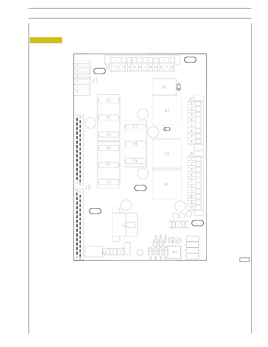
Figure 10
ENGINE INTERFACE BOX
Description
107437
LIST OF COMPONENTS
K1. Power relay with key inserted (+15) - K2. Starting phase signal relay - K3. Starting relay - K4. Relay for pre-heating
resistance enabling - JP1. Jumper to select frequency (jumper on 1-2= 60Hz - jumper on 2-3= 50Hz) - JP2. Jumper for
operating mode selection (bond on 1-2= diagnosis - bond on 2-3= normal operation) - JP3. Jumper to select cold start signal
connection (1-2= connected - 2-3= disconnected) - JP4. Jumper to select heat. function for cold starting (1-2= connected -
2-3= disconnected) - JP5. Jumper for Can Line selection (1-2= Can Line connected - 2-3= Can Line not connected) -
JP6. Not used - JP8. Not used - BP1. Switch for blink-code signal request - LD1. LED signalling blink/code -
F1. 10A fuse for starting engine - F2. 3A fuse for diagnostics - F3. 20A protection fuse for pre-heating resistance -
F4. 30A fuse for electronic control unit - F5. 10A fuse for control panel - F6. 5A fuse for cut-in +15 ON ECU - F7. 20A
protection fuse for fuel filter heater - F8. Not used - F9. Not used - J1. Connector for power connections - J2. Connector
for interface with engine control unit - J3. Connector for interface with control panel - J7. Connector for interface with
control panel - J9. Connector for interface with control panel.
25
CURSOR ENGINES G-DRIVE
SECTION 2 - G-DRIVE APPLICATION
Base - June 2007