Isuzu Trooper (1998-2002 year). Manual - part 895
8D–114
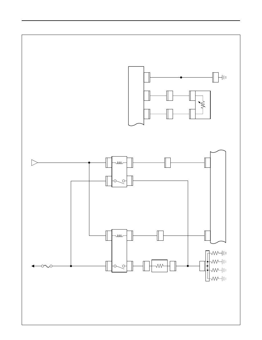
WIRING SYSTEM
Circuit Diagram (LHD)-2
DROPPING
RESIST
OR
GLOW
PLUG
GLOW
RELA
Y
-2
QOS
III
CONTROL
UNIT
GLOW
RELA
Y
-1
C-66
12
H-42
16
1
1
C-60
C-59
3.0
R/W
3.0
B/Y
3.0
B/R
0.5
B/G
0.5
B/G
0.85
B/Y
FL-5 50A
GLOW
C-53
1
C-59
2
1
C-54
BA
TT
.(+)
C-55
1
2
C-55
A
C-66
5
H-41
7
3.0
B/R
0.5
B/L
0.5
B/L
0.85
B/Y
0.85
B/Y
3.0
R/W
C-51
1
C-51
C-52
1
2
2
C-52
12
E-41
E-41
QOS THERMO
SENSOR
(ENGINE)
QOS III CONTROL
UNIT
C-16
0.5
B
0.5
Y
0.5
Y
0.5
B/Y
0.5
B
8
C-66
10
FENDER
-LH
C-66
8
C-66
4
H-4
8
H-4
12
D08RW981