Isuzu Trooper (1998-2002 year). Manual - part 795
TRANSMISSION CONTROL SYSTEM (4L30–E)
7A1–89
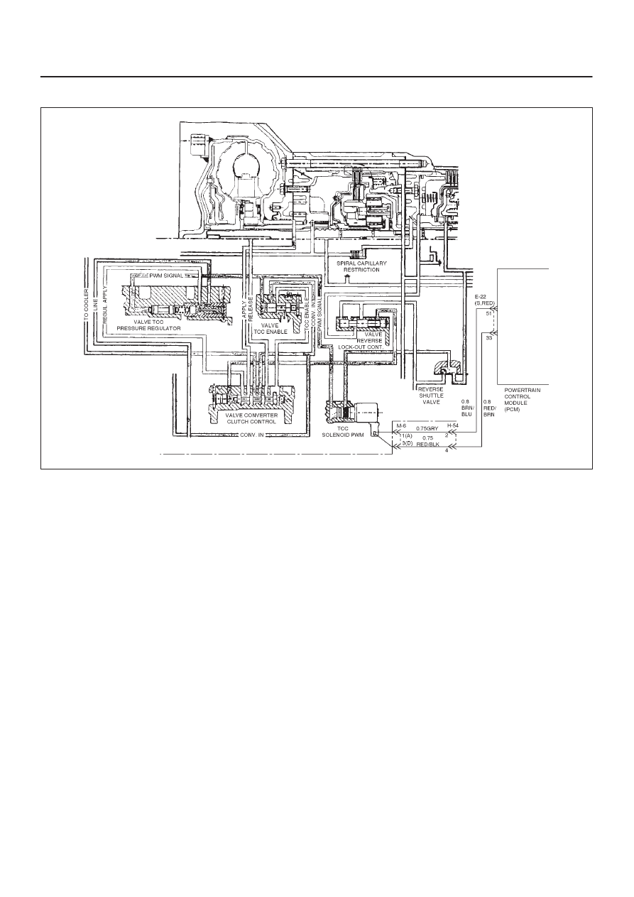
DTC P1870 Transmission Component Slipping (TCC Stuck OFF)
D07R200051
Circuit Description
The PCM monitors the difference in engine speed and
transmission output speed. For example in D3 drive
range with the ECCC commanded, the engine speed
should closely match transmission output speed.
This DTC detects excessive TCC slip when the ECCC is
engaged. This is a type “B” DTC.
Conditions For Setting The DTC
The following conditions are met for three TCC cycles
with reported excessive TCC slip conditions.
D
No OSS DTCs P0722 or P0723.
D
No shift solenoid A DTCs P0751 or P0752 or P0753.
D
No shift solenoid B DTCs P0756 or P0757 or P0758.
D
No TCC solenoid DTCs P0742 or P1860 or P1870.
D
Engine speed is between 1,000 and 3,500 rpm for 0.5
seconds.
D
Gear range is D4.
D
13% < TPS < 99%
D
50 < Engine Torque < 300 N·m
D
TFT is between 20
°
and 150
°
C (68
°
and 302
°
F).
D
TCC slip speed is between 250 rpm and 800 rpm for 3
times 7 seconds.
D
Vehicle speed is between 25 km/h (15 mph) and 225
km/h (158 mph).
D
Speed ratio is between 0.6 and 0.95.
D
ECCC is “ON”.
D
Low (0.8) < TCC Capacity < hi (0.99) for 5 seconds
Action Taken When The DTC Sets
D
Only stored in memory.
D
For lamp illuminate refer to DTC type definition (type
B).
Conditions For Clearing The MIL/DTC
D
The PCM will turn off the MIL and CHECK TRANS
Lamp after three consecutive ignition cycles without a
failure reported.
D
The DTC can be cleared from the PCM history by
using a scan tool.
D
The DTC will be cleared from history when the vehicle
has achieved 40 warmup cycles without a failure
reported.
D
The PCM will cancel the DTC default actions when
the fault no longer exist and the ignition is cycled “off”
long enough to power down the PCM.
Diagnostic Aids
D
Range switch malfunction could set a DTC P1870.
D
A mechanical failure of the shift solenoids, TCC
solenoid, or TCC PWM solenoid could set a DTC
P1870.
D
Internal transmission failures may set a DTC P1870.
D
An intermittent or incorrect engine speed signal may
set a DTC P1870.