Isuzu Trooper (1998-2002 year). Manual - part 721


  Index      Isuzu     Isuzu Trooper - service repair manual 1998-2002 year


Search            


Content   ..  719  720  721  722   ..


Isuzu Trooper (1998-2002 year). Manual - part 721


AUTOMATIC TRANSMISSION (AW30-40LE)

7A–81

256RW014

256RW015

INSTALLATION

To install, follow the removal steps in the reverse order, noting
the following points;

Adjustment of select lever and control rod

1) Place the vehicle on a level surface.

NOTE:  
If the vehicle is not on a level surface, the shift select cable
set position will vary with the movement of the engine. To
prevent possible misadjustment of the cable, the vehicle
must be placed on a level surface.

2) Install the shift control rod (1) to the transfmission select

lever (2), and then place the lever in the "N" position.

3) Set select lever in the "N" position.

4) Push select lever forward and secure it (using a rubber

band (3), etc.) so that pin comes into contact with the wall
of detent plate.

5) Install the shift control rod (1) to the selector lever arm (4).

NOTE:  
Do not apply to threaded portions.

6) After adjustment, operate select lever on a trial basis to

makes sure of its smooth operation and no abnormal
indication in each position.

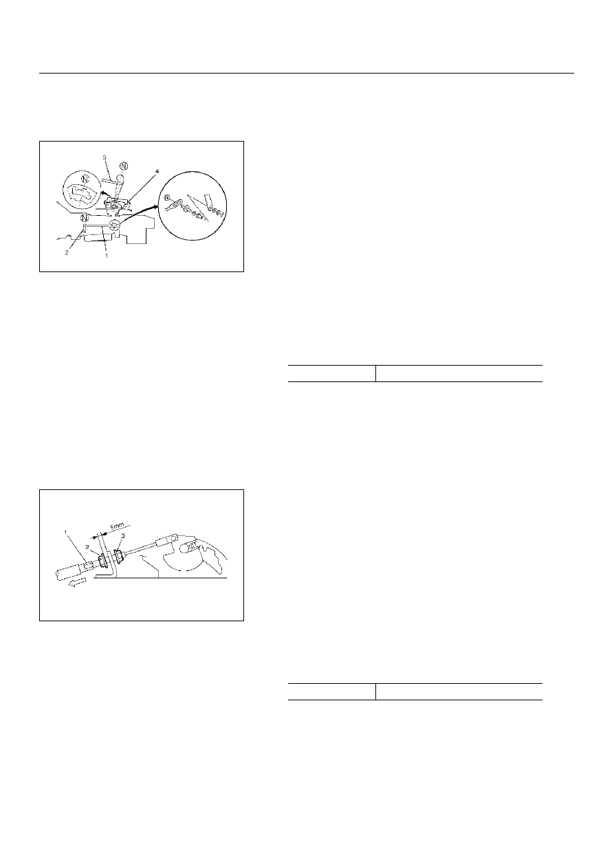
Adjustment of shift lock cable

1) Set ignition key in "LOCK" position and selector lever in "P"

position.

2) Adjust cable screw cap on selector lever side to provide a

gap (slack for cable) of 1–2mm between rod on steering
lock side and stopper.
Adjust cap as follows:
a. Pull screw cap (1) in arrow direction to put off slack of

inner cable.

b. With cable kept as (a), adjust gap between nut (2) and

bracket to 5mm (0.2in).

c. Lock inner cable by turning nut (3) while holding nut (2) in

place.

NOTE:  
Clean the rod threads and do not apply oil to the threaded
portions.

N·m(kg·m / lb·ft)

Nut torque

32 (3.3/24)

N·m(kg·cm / lb·in)

Lock nut torque

3.7 (38/33)

7A–82

AUTOMATIC TRANSMISSION (AW30-40LE)

3) Make sure of proper operation of shift lock through checks

as follows:
a. Selector lever shall not be moved out of "P" position with

ingition key in "Lock" position.

b. Selector lever can be moved out of "P" position with
ignition key in "ON" position only when brake pedal is
depressed.
c. Ignition key can be turned to "LOCK" position only when
selector lever is in "P" position (key can be pulled out).
If (a) and (c) fail, readjust cable. If (b) fails, readjust
connector wiring and brake pedal switch.

AUTOMATIC TRANSMISSION (AW30-40LE)

7A–83

826RY00005

826RY00006

249RY00011

249RY00012

TRANSMISSION CONTROL MODULE
(TCM)

REMOVAL

Preparation:

Disconnect negative (–) battery cable.

1. Disconnect the TCM harness connectors.

2. Remove fixing nuts (3 pieces) and TCM from the bracket.

INSTALLATION

To install, follow the removal steps in reverse order.

SHIFT SOLENOID AND LOCK-UP 
SOLENOID

REMOVAL

Preparation:

• Disconnect negative (–) battery cable.

• Remove the rear sound cover.

• Drain the fluid.

Refer to

 "ATF REPLACEMENT" in this section.

1. Remove the nineteen bolts and oil pan.

2. Remove the oil strainer assembly.

3. Disconnect the solenoid wiring connectors from the shift

solenoid S1(1), S2(2) and lock-up solenoid (3).

4. Remove each retaining bolts and solenoids.

INSTALLATION

To install, follow the removal steps in reverse order noting the
following point;

Tprque

N·m (kg·cm/lb·in)

Solenoid S1, S2 bolt

7 (70/61)

Lock-up solenoid bolt

10 (100/87)

7A–84

AUTOMATIC TRANSMISSION (AW30-40LE)

VALVE BODY ASSEMBLY AND PRESSERE CONTOROL SOLENOID

244RY00009

 244RY00003

REMOVAL

Preparation:

• Disconnect negative (–) battery cable.

• Remove the rear sound cover.

• Drain the fluid.

Refer to

 "ATF REPLACEMENT" in this section.

1. Remove the nineteen bolts and oil pan.

2. Remove the oil strainer assembly.

3. Disconnect the soleniod wiring connectors from the

solenoids.

4. Remove the twenty botls from the valve body.

5. Remove the valve body assembly and pressure

control solenoid.

• When removing valve body assembly from the

transmission case, loosen the solenoid clamp bolt
and remove the pressure control solenoid from
the upper valve body assembly.
Also disconnect the harness connector from the
pressure control solenoid.


Content   ..  719  720  721  722   ..