Isuzu Trooper (1998-2002 year). Manual - part 720


  Index      Isuzu     Isuzu Trooper - service repair manual 1998-2002 year


Search            


Content   ..  718  719  720  721   ..


Isuzu Trooper (1998-2002 year). Manual - part 720


AUTOMATIC TRANSMISSION (AW30-40LE)

7A–77

310RW020

F07RY00017

F07RY00018

BRAKE SIGNAL INSPECTION

Check that the brake light comes on when the brake pedal is
depressed.

VEHICLE SPEED SENSOR INSPECTION

1. Connect the Vehicle speed sensor connector terminal (1) to

the battery (+) terminal and terminal (2) to the battery (-)
terminal.

2. Connect a resistance of 1.3k ohm to 5k ohm (1.4W or

more) between terminals (1) and (3).

NOTE:  
Be extremely careful not to connect the battery (+) terminal
to the terminal (3)
This may damage the vehicle speed sensor.

3. Rotate the shaft of the vehicle speed sensor slowly and

measure the voltage at both ends with a digital tester.

Replace the sensor when the result of inspection is found
abnormal.

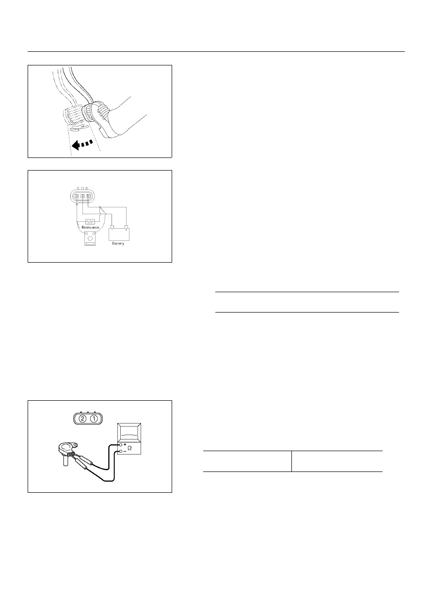
INPUT AND OUTPUT REVOLUTION
SENSOR INSPECTION

Use an ohmmeter to measure the resistance between 
terminals 1 and 2.

The voltage, with one rotation of shaft, fluctuates four 
times in the following range: 10 to 14V 

⇔ 

2V or less.

Standard resistance

560 – 680

 (20

°

C)

610 – 740

 (40

°

C)

7A–78

AUTOMATIC TRANSMISSION (AW30-40LE)

F07RY00019

225RY00001

220RY00001

244RX00001

PATTERN SELECT SWITCH INSPECTION

Inspect that there is continuity between each terminals.

OVERDRIVE OFF SWITCH INSPECTION

Inspect that there is continuity between terminals 2 and 4.

SOLENOID INSPECTION

1. Resistance check

• Using an ohmmeter, check the resistance between each

terminals (S1/S2/SL) and body.

• Using an ohmmeter, check the resistance between

terminals (STH) and (STHG).

 
NOTE:  
If the pressure contorl solenoid resistance is not within
specification, replace the valve body assembly.

2. Operation Check

Check the solenoid operation by blowing into an oil hole as
shown in the figure.

Solenoid S1 and S2 (Normal close type)

Solenoid S1, S2 and Lock-up 

solenoid resistance

11 - 15

Ω 

(20

°

C)

12 - 16 

Ω 

(40

°

C)

Pressure control solenoid 

resistance

5 - 5.6

Ω 

(20

°

C)

5.4 - 6.1 

Ω 

(40

°

C)

When battery terminal is 

disconnected

No air leaks

When battery terminal is 

connected

Air passes through

AUTOMATIC TRANSMISSION (AW30-40LE)

7A–79

244RY00005

101RY00004

249RW003

242RW013

Look-up solenoid (Normal open type)

THROTTLE POSITION SENSOR 
INSPECTION

1. Turn the starter switch to the "ON" position.

2. Measure the voltage between throttle position sensor

connector terminals 2 (output) and 3 (ground).

NOTE:

• Do not remove the sensor connector.

• Make sure that power source (4.75-5.25V) is measured

between terminals 1 and 3 before measurement at step
2).

ATF TEMPERATURE SENSOR 
INSPECTION

1. Disconnect the front side ATF cooler pipe from the elbow

and remove the elbow.

2. Remove the ATF temperature sensor from the transmission

case.

3. Place the ATF temperature sensor in a container of ATF.

4. Measure the resistance between each terminals.

5. If either of the measured values exceeds the specified,

replace the ATF temperature sensor.

N

·

m (kg

·

m/ lb

·

ft)

When battery terminal is 

disconnected

Air passes through

When battery terminal is 

connected

No air leaks

Throttle position

Voltage (V)

Idle

0.25-0.45

WOT

3.74-4.56

Resistance

0.5 - 30 k

Ω 

(0

°

C - 120

°

C)

Torque

15 (1.5/11)

7A–80

AUTOMATIC TRANSMISSION (AW30-40LE)

256RY00001

256RW012

256RW013

SELECTOR LEVER

INSPECTION

1. Make sure that when the selector lever is shifted from "P" to

"L", a "clicking" can be felt at each shift position. Make sure
that the gear corresponds to that of the position plate
indicator.

2. Check to see if the shifter lever can be shifted as shown.

REMOVAL

Preparation:

Diconnect negative (–) battery cable.

1. Transfer Control Lever Knob

2. Front Console

Disconnect wiring harness connectors.

3. Selector Lever Assembly

1) Disconnect shift lock cable from the selector lever

assembly side.

2) Disconnect wiring harness connectors.

3) Disconnect shift control rod from the selector lever

assembly side.


Content   ..  718  719  720  721   ..