Isuzu Trooper (1998-2002 year). Manual - part 687
7A–40
AUTOMATIC TRANSMISSION (4L30–E)
Solenoid (Adapter Case Valve Body)
Removal
1. Raise the vehicle and support it on jack stands.
2. Disconnect battery ground cable.
3. Drain fluid.
4. Remove adapter case oil pan twelve fixing 10 mm
screws, adapter case oil pan, and gasket.
NOTE: Oil pan still contains transmission fluid. Place a
large drain container under the oil pan and drain the fluid
carefully.
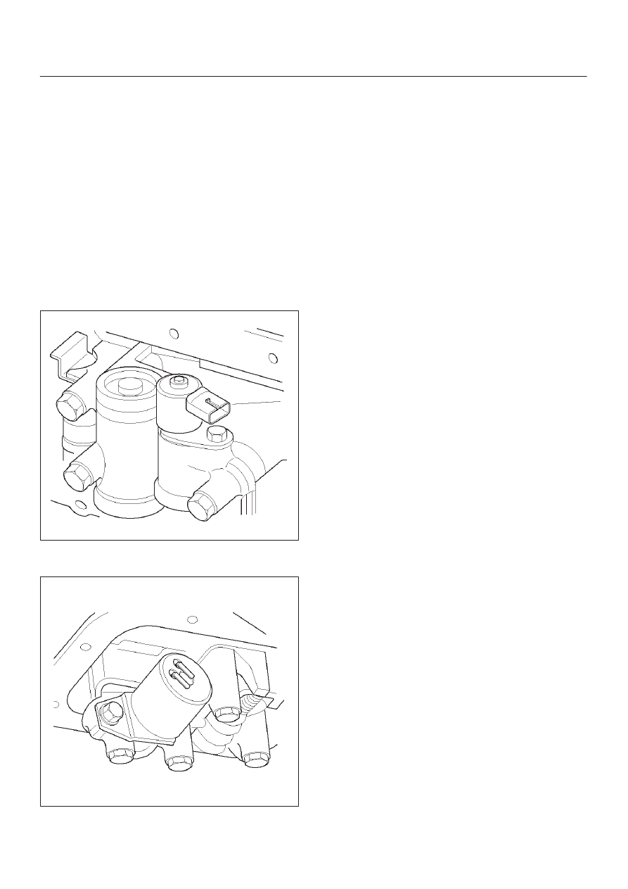
5. Disconnect wiring harness from force motor solenoid
and converter clutch PWM solenoid. Pull only on
connectors, not on wiring harness.
6. Remove 11 mm bolt, bracket and converter clutch
PWM solenoid with two O–rings.
210RY001
7. Remove 11 mm bolt, retainer, and force motor
solenoid.
210RW009
Installation
1. Install force motor solenoid, retainer, and 11 mm bolt
to adapter case valve body. Tighten the bolt to the
specified torque.
Torque: 10 N
•
m (1.0 kg·m/87 Ib in)
2. Install converter clutch PWM solenoid with two O–
rings, bracket, and 11 mm bolt to adapter case valve
body. Tighten the bolt to the specified torque.
Torque : 10 N
•
m (1.0 kg·m/87 Ib in)
3. Connect wiring harness assembly to solenoids.
4. Install adapter case oil pan, new gasket, and twelve
10 mm screws. Tighten the screws to the specified
torque.
Torque : 11 N
•
m (1.1 kg·m/96 Ib in)
5. Fill transmission through overfill screw hole oil pan,
using ATF DEXRON
–III. Refer to Changing
Transmission Fluid in this section.
6. Connect battery ground cable.