Isuzu Trooper (1998-2002 year). Manual - part 651
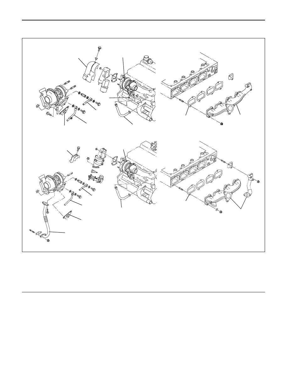
6J – 4 INDUCTION
TURBOCHARGER
9
5
9
8
For Europe
8
7
5
6
3
2
1
4
7
4
2
1
3
6
Legend
(1)
Exhaust Manifold
(2)
Gasket
(3)
Turbocharger Assembly
(4)
Water Hose
(5)
Water Hose
(6)
Heat Protector
(7)
Oil Pipe
(8)
Oil Pipe
(9)
Gasket
025R200004