Isuzu Trooper (1998-2002 year). Manual - part 649
6G – 6 ENGINE LUBRICATION
OIL COOLER ASSEMBLY
REMOVAL
1. Disconnect battery ground cable.
2. Drain engine coolant.
3. Remove front exhaust pipe.
4. Remove heat protector.
5. Remove exhaust valve assembly.
6. Oil cooler assembly.
1) Remove water hose from water inlet and outlet
side.
2) Cloth should be put under the oil cooler to
prevent oil from flowing out.
3) Loosen fixing bolt then remove oil cooler
assembly.
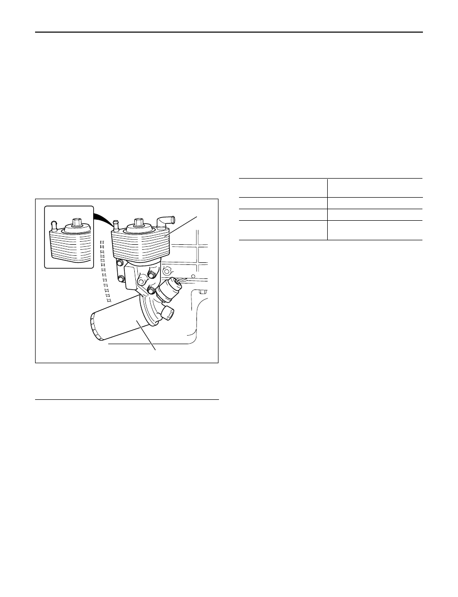
Legend
(1) Oil cooler assembly
(2) Oil filter assembly
INSPECTION AND REPAIR
1. Inspect for corrosion, wear, and breaks on the oil
cooler core.
2. If a problem is found on the oil cooler core, the oil
cooler assembly must be replaced.
INSTALLATION
1. Oil cooler assembly
1) Tighten oil cooler fixing bolt to the specified
torque and install water hoses.
Torque: 29 N·m (3.0 kg·m / 22 lb ft)
2. Install exhaust valve assembly to turbocharger
assembly and tighten to the specified torque.
Torque: 27 N·m (2.8 kg·m / 20 lb ft)
3. Install front exhaust pipe to the exhaust valve.
Torque:
67 N·m (6.8 kg·.m / 49 lb ft)
(At exhaust valve side)
43 N·m (4.4 kg·m / 32 lb ft)
(At center exhaust pipe side)
4. Install heater protector.
5. Fill engine coolant.
6. Connect battery ground cable.
7. Start engine and carefully check for leakage of oil
and coolant.
OIL COOLER SPECIFICATIONS
Cooling method
Water cooled
Multi plate type
Heat exchange Area
0.323 m
2
Heat exchange capacity
>11,300 kcl/h
Relief Valve opening
245 Kpa (2.5 kg/cm
2
/36 psi)
pressure
OIL FILTER
REMOVAL
1. Put container under the oil filter to prevent oil from
the oil filter from flowing out.
2. Use filter wrench to remove oil filter.
Filter wrench: 5-8840-0203-0
INSTALLATION
1. Apply engine oil thinly to oil filter O-ring.
2. Tighten oil filter by hand until O-ring comes in
contact with the sealing surface.
3. Use filter wrench to tighten oil filter one turn and 1/8
turn.
4. Start engine and carefully check for oil leakage from
oil filter.
SUB OIL FILTER
The sub oil filter requires no servicing until the
replacement interval is reached.
The element is designed to provide special filtering
efficiency until it becomes due for replacement.
It is recommended to check and replace the sub oil filter
when the engine is being overhauled or if it is broken
inside the engine.
For Europe
1
2
050R200001