Isuzu Trooper (1998-2002 year). Manual - part 643


  Index      Isuzu     Isuzu Trooper - service repair manual 1998-2002 year


Search            


Content   ..  641  642  643  644   ..


Isuzu Trooper (1998-2002 year). Manual - part 643


6E–220

4JX1–TC ENGINE DRIVEABILITY AND EMISSIONS

Installation Procedure

1. Install the EVRV.

035RW064

2. Connect the EVRV hose and the EVRV connector.

035RW065

3. Connect the negative battery cable.

Wiring and Connectors

Wiring Harness Service

The ECM harness electrically connects the ECM to the
various solenoids, switches and sensors in the vehicle
engine compartment and passenger compartment.
Replace wire harnesses with the proper part number
replacement.
Because of the low amperage and voltage levels utilized
in powertrain control systems, it is essential that all wiring
in environmentally exposed areas be repaired with crimp
and seal splice sleeves.

The following wire harness repair information is intended
as a general guideline only.  Refer to 

Chassis Electrical for

all wire harness repair procedures.

Connectors and Terminals

Use care when probing a connector and when replacing
terminals.  It is possible to short between opposite
terminals.  Damage to components could result.  Always
use jumper wires between connectors for circuit
checking.  NEVER probe through Weather-Pack seals.
Use an appropriate connector test adapter kit which
contains an assortment of flexible connectors used to
probe terminals during diagnosis.  Use an appropriate
fuse remover and test tool for removing a fuse and to
adapt the fuse holder to a meter for diagnosis.
Open circuits are often difficult to locate by sight because
oxidation or terminal misalignment are hidden by the
connectors.  Merely wiggling a connector on a sensor, or
in the wiring harness, may temporarily correct the open
circuit.  Intermittent problems may also be caused by
oxidized or loose connections.
Be certain of the type of connector/terminal before
making any connector or terminal repair.  Weather-Pack
and Com-Pack III terminals look similar, but are serviced
differently.

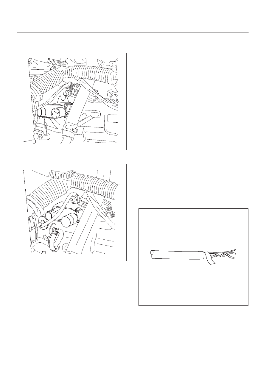
Wire Harness Repair: Twisted

Shielded Cable

Removal Procedure

1. Remove the outer jacket.
2. Unwrap the aluminum/mylar tape.  Do not remove the

mylar.

047

6E–221

4JX1–TC ENGINE DRIVEABILITY AND EMISSIONS

3. Untwist the conductors.
4. Strip the insulation as necessary.

048

Installation Procedure

1. Splice the wires using splice clips and rosin core

solder.

2. Wrap each splice to insulate.
3. Wrap the splice with mylar and with the drain

(uninsulated) wire.

049

4. Tape over the whole bundle to secure.

050

Twisted Leads

Removal Procedure

1. Locate the damaged wire.
2. Remove the insulation as required.

051

6E–222

4JX1–TC ENGINE DRIVEABILITY AND EMISSIONS

Installation Procedure

1. Use splice clips and rosin core solder in order to splice

the two wires together.

052

2. Cover the splice with tape in order to insulate it from

the other wires.

053

3. Twist the wires as they were before starting this

procedure.

054

4. Tape the wires with electrical tape.  Hold in place.

055

6E–223

4JX1–TC ENGINE DRIVEABILITY AND EMISSIONS

Weather-Pack Connector

Tools Required

5-8840-0388-0 Weather-Pack II Terminal Remover

Removal Procedure

A Weather-Pack connector can be identified by a rubber
seal at the rear of the connector.  This engine room
connector protects against moisture and dirt, which could
from oxidation and deposits on the terminals.  This
protection is important, because of the low voltage and
the low amperage found in the electronic systems.

1. Open the secondary lock hinge on the connector.

070

2. Use tool 5-8840-0388-0 or the equivalent to remove

the pin and the sleeve terminals.  Push on
5-8840-0388-0 to release.

NOTE: Do the use an ordinary pick or the terminal may
be bent or deformed.  Unlike standard blade terminals,
these terminals cannot be straightened after they have
been improperly bent.

071

3. Cut the wire immediately behind the cable seal.

072

Installation Procedure

Make certain the connectors are properly seated and all
of the sealing rings are in place when you reconnect the
leads.  The secondary lock hinge provides a backup
locking feature for the connector.  The secondary lock
hinge is used for added reliability.  This flap should retain
the terminals even if the small terminal lock tangs are not
positioned properly.
Do not replace the Weather-Pack connections with
standard connections.  Read the instructions provided
with the Weather-Pack connector and terminal packages.

1. Replace the terminal.
2. Slip the new seal onto the wire.
3. Strip 5 mm (0.2”) of insulation from the wire.
4. Crimp the terminal over the wire and the seal.

073


Content   ..  641  642  643  644   ..