Isuzu Trooper (1998-2002 year). Manual - part 626
6E–152
4JX1–TC ENGINE DRIVEABILITY AND EMISSIONS
Diagnostic Trouble Code (DTC) P0502 (Flash DTC 24)
VSS (Vehicle Speed Sensor) No Signal
060RW136
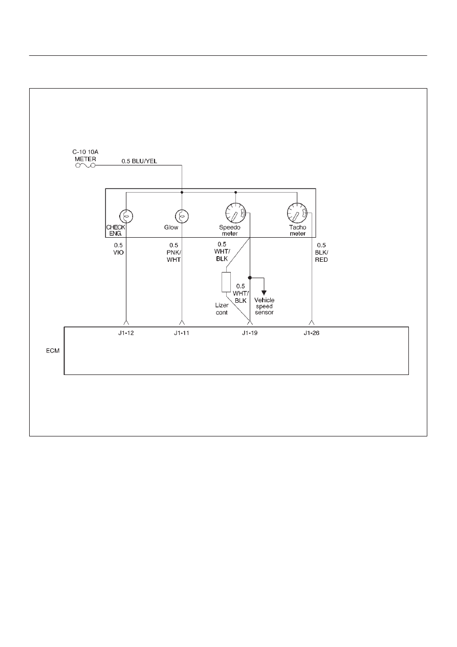
Circuit Description
The vehicle speed sensor has a magnet rotated by the
transmission output shaft. Attached to the sensor is a hall
effect circuit the interacts with the magnetic field treated
by the rotating magnet. A 12-volt operating supply for the
speed sensor hall circuit is supplied from the meter fuse.
The VSS pulses to ground the 9-volt signal sent from the
engine control module (ECM) on the reference circuit.
The ECM interprets vehicle speed by the number of
pulses to ground per second on the reference circuit.
Action Taken When the DTC Sets
D
The ECM will illuminate the malfunction indicator lamp
(MIL) the first time the fault is detected.
D
The ECM will store conditions which were present
when the DTC was set as Freeze Frame and in the
Failure Records data.
Conditions for Clearing the MIL/DTC
D
DTC P0502 can be cleared by using the Tech 2 “Clear
Info” function or by disconnecting the ECM battery
feed.