Isuzu Trooper (1998-2002 year). Manual - part 624
6E–144
4JX1–TC ENGINE DRIVEABILITY AND EMISSIONS
Diagnostic Trouble Code (DTC) P1485 (Flash DTC 74)
ITP (Intake Thorottle Position) Sensor Low Voltage
060RW134
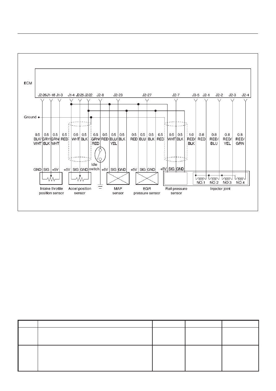
Circuit Description
The intake throttle position (ITP) sensor circuit provides a
voltage signal that changes relative to throttle blade
angle.
Action Taken When the DTC Sets
D
The ECM will illuminate the malfunction indicator lamp
(MIL) the first time the fault is detected.
D
The ECM will store conditions which were present
when the DTC was set as Freeze Frame and in the
Failure Records data.
Conditions for Clearing the MIL/DTC
D
DTC P1485 can be cleared by using the Tech 2 “Clear
Info” function or by disconnecting the ECM battery
feed.
Diagnostic Aids
Check for the following conditions:
D
Poor connection at ECM – Inspect harness connectors
for backed-out terminals, improper mating, broken
locks, improperly formed or damaged terminals, and
poor terminal-to-wire connection.
D
Damaged harness – Inspect the wiring harness for
damage.
If the harness appears to be OK, observe the
throttle position display on the Tech 2 while
moving connectors and wiring harnesses related
to the ITP sensor. A change in the display will
indicate the location of the fault.
If DTC P1485 cannot be duplicated, the information
included in the Failure Records data can be useful in
determining vehicle mileage since the DTC was last set.
DTC P1485 –ITP Sensor Low Voltage
Step
Action
Value(s)
Yes
No
1
Was the “On-Board Diagnostic (OBD) System Check”
performed?
—
Go to
Step 2
Go to
OBD
System
Check
2
1. Ignition “ON,” engine “OFF.”
2. With the throttle closed by the hand, observe the
“ITP Sensor” display on the Tech 2.
Is the “ITP Sensor” below the specified value?
0.22 V
Go to
Step 4
Go to
Step 3