Isuzu Trooper (1998-2002 year). Manual - part 612
6E–96
4JX1–TC ENGINE DRIVEABILITY AND EMISSIONS
Diagnostic Trouble Code (DTC) P0198 (Flash DTC 16)
Oil Temp Sensor High Voltage
060RW129
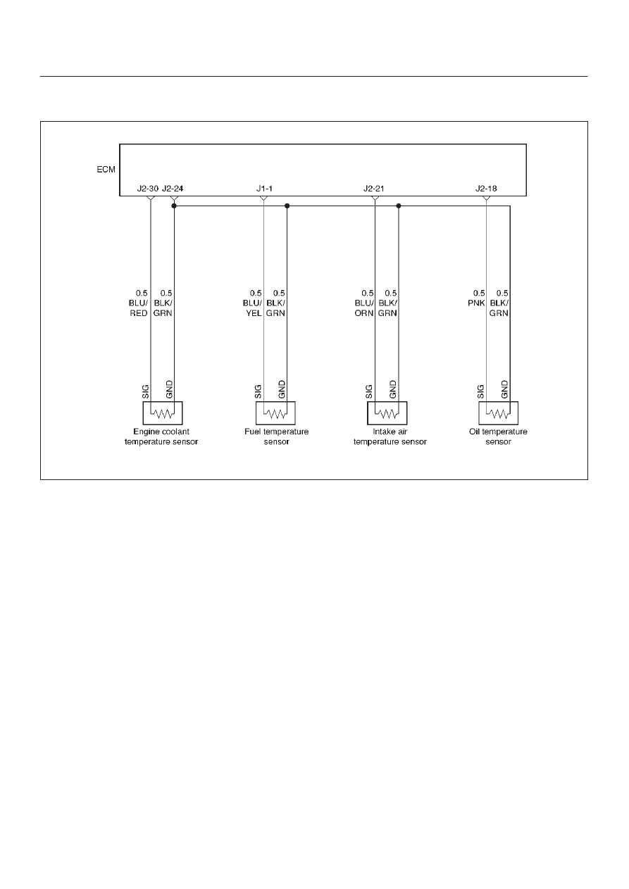
Circuit Description
The engine oil temperature (OT) sensor is a thermistor
mounted in the oil rail. The Engine Control Module ECM
applies a voltage (about 5 volts) through a pull-up resistor
to the ECT signal circuit. When the engine oil is cold, the
sensor (thermistor) resistance is high, therefore the ECM
will measure a high signal voltage. As the engine oil
warms, the sensor resistance becomes lower, and the OT
signal voltage measured at the ECM drops.
Action Taken When the DTC Sets
D
The ECM will store conditions which were present
when the DTC was set as Freeze Frame and in the
Failure Records data.
Conditions for Clearing the MIL/DTC
D
DTC P0198 can be cleared by using the Tech 2 “Clear
Info” function or by disconnecting the ECM battery
feed.
Diagnostic Aids
Check for the following conditions:
D
Poor connection at ECM – Inspect harness connectors
for backed-out terminals, improper mating, broken
locks, improperly formed or damaged terminals, and
poor terminal-to-wire connection.
D
Damaged harness – Inspect the wiring harness for
damage. If the harness appears to be OK, observe the
OT display on the Tech 2 while moving connectors and
wiring harnesses related to the OT sensor. A change
in the OT display will indicate the location of the fault.
If DTC P0198 cannot be duplicated, the information
included in the Failure Records data can be useful in
determining vehicle mileage since the DTC was last set.
If it is determined that the DTC occurs intermittently.