Isuzu Trooper (1998-2002 year). Manual - part 611
6E–92
4JX1–TC ENGINE DRIVEABILITY AND EMISSIONS
Diagnostic Trouble Code (DTC) P1196 (Flash DTC 62)
Rail Pressure System High Warning
060RW178
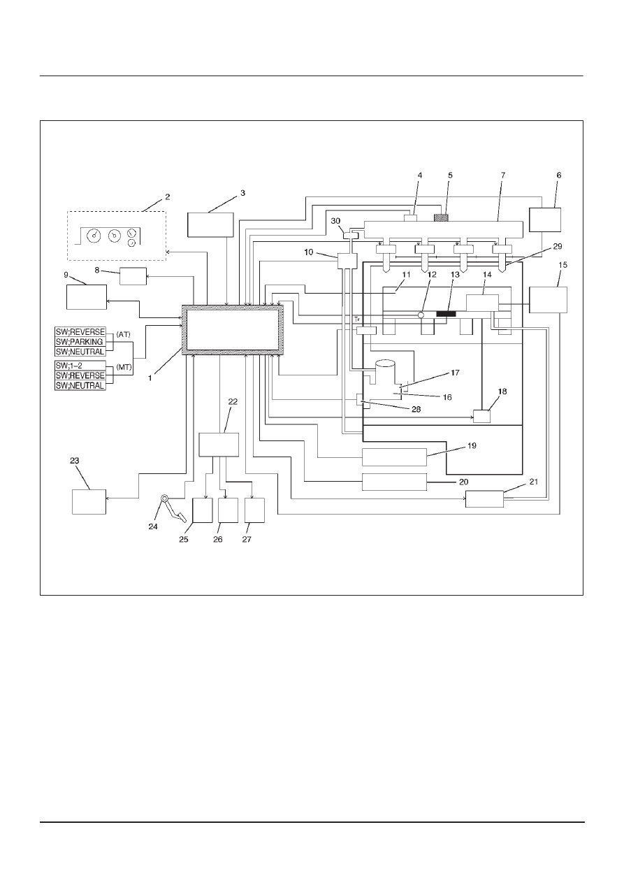
Legend
(1) ECM
(2) Meter Panel
(3) Battery
(4) Oil Temp Sensor
(5) Rail Pressure Sensor
(6) Glow Relay
(7) Oil Rail
(8) Tech–2
(9) A/C Comp Relay
(10) RPCV
(11) Intake Air Temp Sensor
(12) Engine Coolant Temp Sensor
(13) MAP Sensor
(14) EGR Valve
(15) EGR Pressure Sensor
(16) High Pressure Oil Pump
(17) Fuel Pump
(18) VSV
(19) EXH Throttle VSV1
(20) EXH Throttle VSV2
(21) EVRV
(22) Engine Harness Connector
(23) QWS Relay
(24) AP Sensor
(25) T.O.D
(26) ECT
(27) OBD
(28) TDC
(29) Injector
(30) Edge Filter