Isuzu Trooper (1998-2002 year). Manual - part 603
6E–60
4JX1–TC ENGINE DRIVEABILITY AND EMISSIONS
Diagnostic Trouble Code (DTC) P0112 (Flash DTC 23)
IAT Sensor Circuit Low Voltage
060RW129
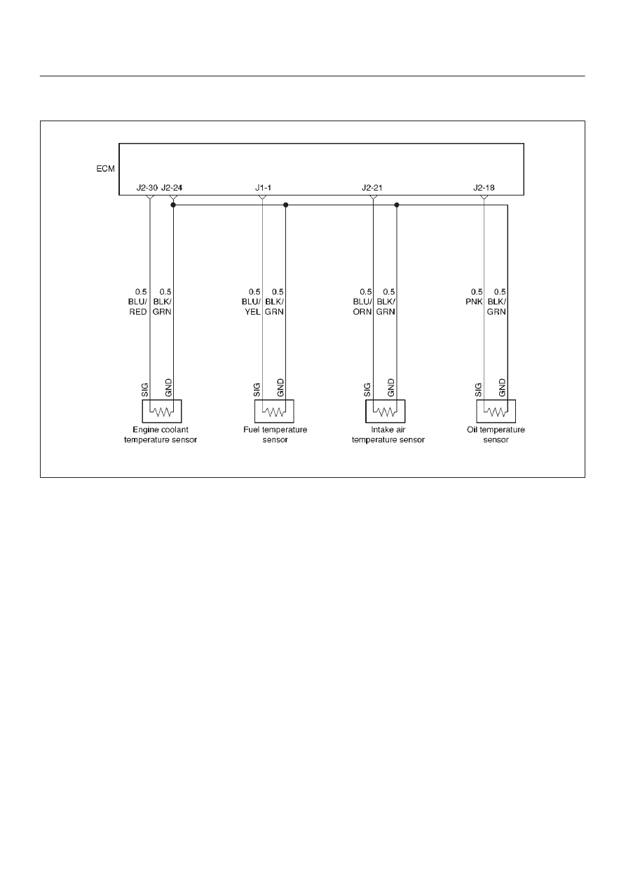
Circuit Description
The Intake air temperature (IAT) sensor is a thermistor
which measures the temperature of the air entering the
engine. The Engine Control Module ECM applies 5 volts
through a pull-up resistor to the IAT sensor. When the
intake air is cold, the sensor resistance is high and the
ECM will monitor a high signal voltage on the IAT signal
circuit. If the intake air is warm, the sensor resistance is
lower, causing the ECM to monitor a lower voltage. DTC
P0112 will set when the ECM detects an excessively low
signal voltage on the Intake air temperature sensor signal
circuit.
Action Taken When the DTC Sets
D
The ECM will illuminate the malfunction indicator lamp
(MIL) the first time the fault is detected.
D
The ECM will store conditions which were present
when the DTC was set as Freeze Frame and in the
Failure Records data.
Conditions for Clearing the MIL/DTC
D
DTC P0112 can be cleared by using the Tech 2 “Clear
Info” function or by disconnecting the ECM battery
feed.
Diagnostic Aids
Check for the following conditions:
D
Poor connection at ECM – Inspect harness connectors
for backed-out terminals, improper mating, broken
locks, improperly formed or damaged terminals, and
poor terminal-to-wire connection.
D
Damaged harness – Inspect the wiring harness for
damage. If the harness appears to be OK, observe the
IAT display on the Tech 2 while moving connectors and
wiring harnesses related to the IAT sensor. A change
in the IAT display will indicate the location of the fault.
If DTC P0112 cannot be duplicated, the information
included in the Failure Records data can be useful in
determining vehicle mileage since the DTC was last set.