Isuzu Trooper (1998-2002 year). Manual - part 595


  Index      Isuzu     Isuzu Trooper - service repair manual 1998-2002 year


Search            


Content   ..  593  594  595  596   ..


Isuzu Trooper (1998-2002 year). Manual - part 595


6E–28

4JX1–TC ENGINE DRIVEABILITY AND EMISSIONS

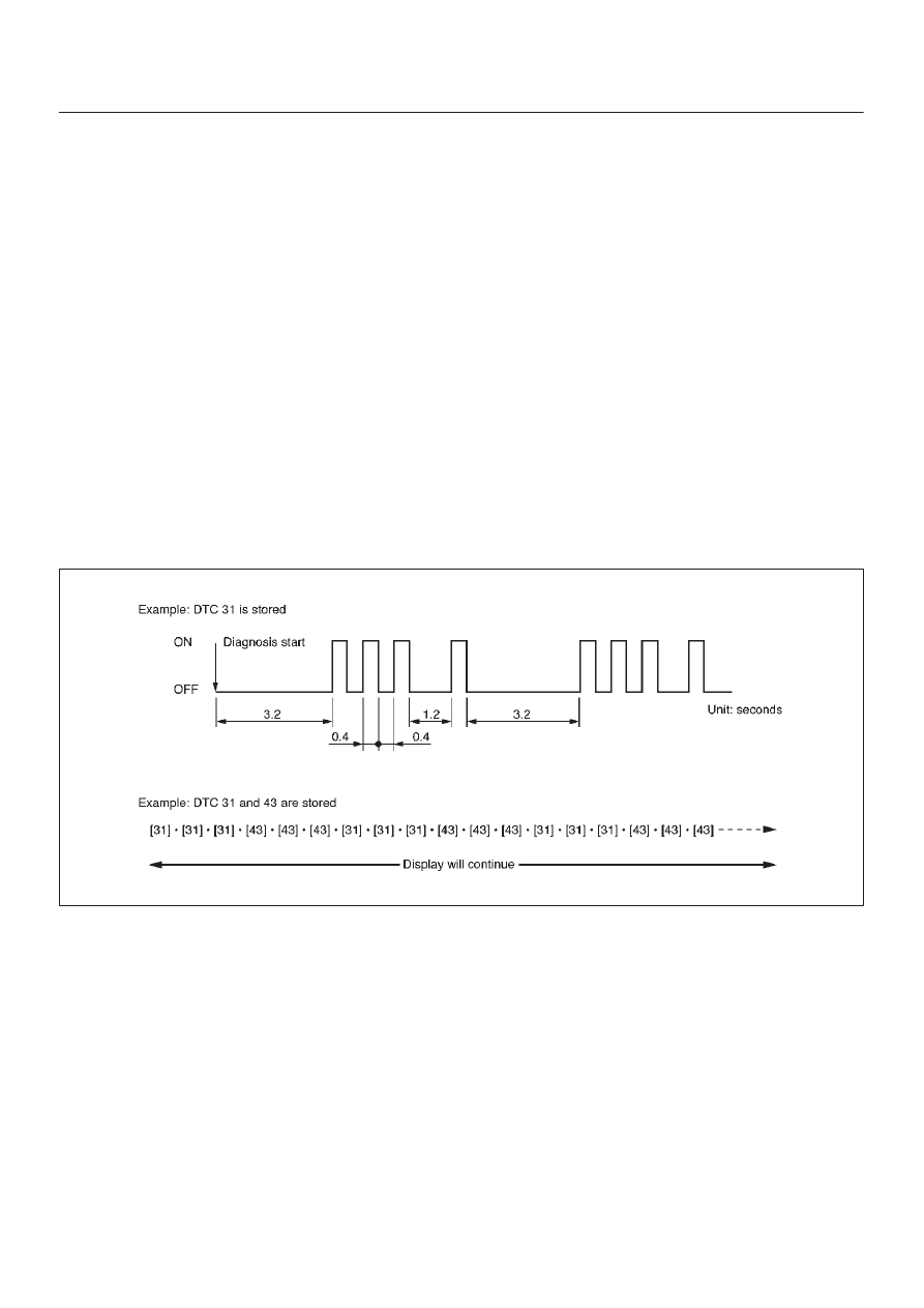
in the ECM’s memory, the DTC(s) will be output from the
lowest to the highest, with each DTC being displayed
three times.
The DTC display will continue as long as the DLC is
shorted.

Reading Diagnostic Trouble Codes Using
a TECH 2

The procedure for reading diagnostic trouble code(s) is to
used a diagnostic Tech 2.  When reading DTC(s),  follow
instructions supplied by Tech 2 manufacturer.
For the 1998 model year, Isuzu dealer service
departments will continue to use Tech 2.

Clearing Diagnostic Trouble Codes

IMPORTANT:

Do not clear DTCs unless directed to do

so by the service information provided for each diagnostic
procedure.  When DTCs are cleared, the Freeze Frame
and Failure Record data which may help diagnose an
intermittent fault will also be erased from memory.
If the fault that caused the DTC to be stored into memory
has been corrected, the Diagnostic Executive will begin to
count the “warm-up” cycles with no further faults
detected, the DTC will automatically be cleared from the
ECM memory.

To clear Diagnostic Trouble Codes (DTCs), use the Tech
2 “clear DTCs” or “clear information” function.  When
clearing DTCs follow instructions supplied by the Tech 2
manufacturer.
When a Tech 2 is not available, DTCs can also be cleared
by disconnecting 

one of the following sources for at least

thirty (30) seconds.

NOTE: To prevent system damage, the ignition key must
be “OFF” when disconnecting or reconnecting battery
power.

D

The power source to the control module.  Examples:
fuse, pigtail at battery ECM connectors etc.

D

The negative battery cable.  (Disconnecting the
negative battery cable will result in the loss of other
on-board memory data, such as preset radio tuning).

060RW169

6E–29

4JX1–TC ENGINE DRIVEABILITY AND EMISSIONS

Tech 2 Scan Tool

From 98 MY, Isuzu dealer service departments are
recommended to use Tech 2. Please refer to Tech 2 user
guide.

901RW257

Legend

(1) PCMCIA Card
(2) SAE 16/19 Adaptor

(3) DLC Cable
(4) Tech–2

6E–30

4JX1–TC ENGINE DRIVEABILITY AND EMISSIONS

Getting Started

D

Before operating the Isuzu PCMCIA card with the
Tech 2, the following steps must be performed:

1. The Isuzu 98 System PCMCIA card (1) inserts into

the Tech 2 (5).

2. Connect the SAE 16/19 adapter (3) to the DLC cable

(4).

3. Connect the DLC cable to the Tech 2 (5)
4. Make sure the vehicle ignition is off.
5. Connect the Tech 2 SAE 16/19 adapter to the vehicle

DLC.

6. The vehicle ignition turns on.
7. Verify the Tech 2 power up display.

012RW105

NOTE: The RS232 Loop back connector is only to use for
diagnosis of Tech 2 and refer to user guide of the Tech 2.

Operating Procedure

The power up screen is displayed when you power up the
tester with the Isuzu systems PCMCIA card. Follow the
operating procedure below.

060RW014

6E–31

4JX1–TC ENGINE DRIVEABILITY AND EMISSIONS

060RW120

Menu

D

The following table shows, which functions are used
the available equipment versions.

F0: Diagnostic Trouble Codes

F0: Read DTC Info Ordered By Priority

F1: Read DTC Info As Stored By ECU

F2: Clear DTC Information

F3: Freeze Frame / Failure Records

F1: Data Display

F2: Snapshot

F3: Actuator Tests

F0: Checklight

F1: Glow Time Lamp

F2: EGR Switching Valve

F3: Exhaust Switching Valve 1

F4: Exhaust Switching Valve 2

F4: Miscellaneous Tests

F0: Throttle Motor Control

F1: Rail Pressure Control

F2: EGR Regulating Valve Control

F3: Rail Pressure Control Valve

F4: Injector Balance Test

F5: Programming

F0: Injector Calibration

(F1: Rail Pressure Calibration)


Content   ..  593  594  595  596   ..