Isuzu Trooper (1998-2002 year). Manual - part 592


  Index      Isuzu     Isuzu Trooper - service repair manual 1998-2002 year


Search            


Content   ..  590  591  592  593   ..


Isuzu Trooper (1998-2002 year). Manual - part 592


6E–16

4JX1–TC ENGINE DRIVEABILITY AND EMISSIONS

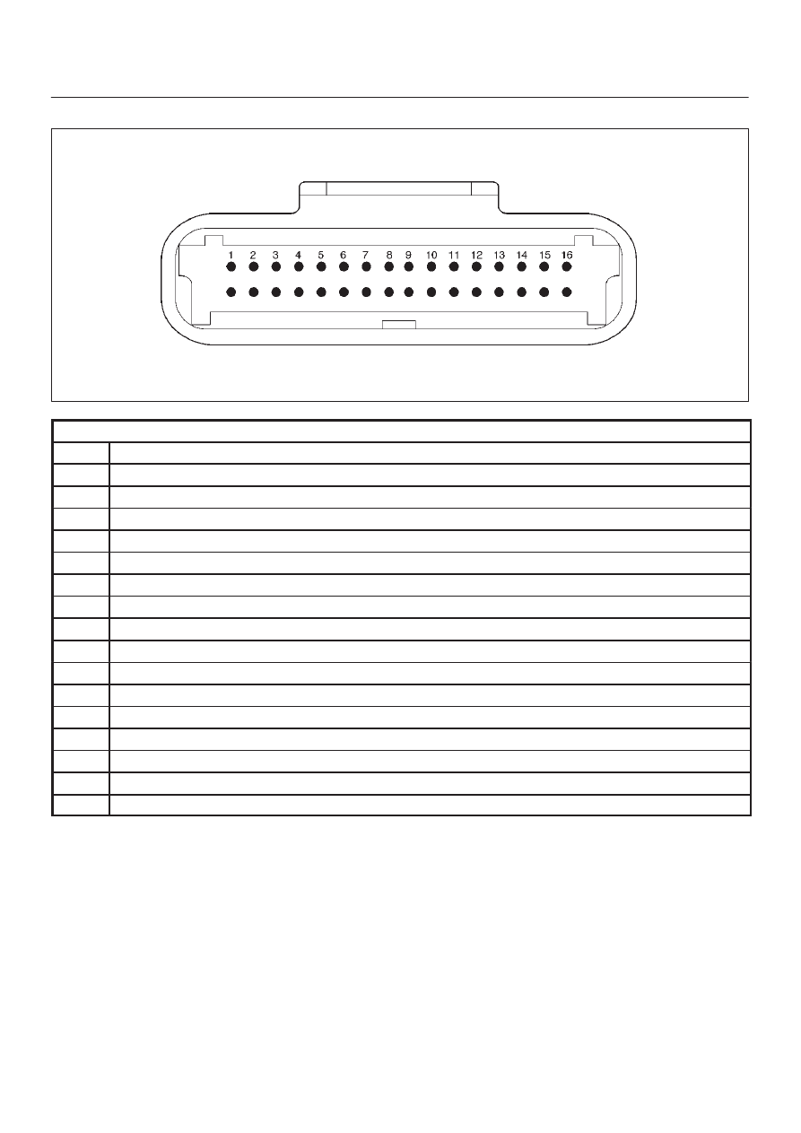
ECM Pinout Table, 32-Way Connector – J2 BLUE – Upper

060RW138

J2 – BLUE

PIN

SIGNAL

1

INJECTOR A RTN

2

INJECTOR B RTN

3

INJECTOR C RTN

4

INJECTOR D RTN

5

CLASS 2

6

SDATA

7

RAIL OIL PRESSURE

8

IDLE SW

9

IGN SW

10

BATTERY

11

QUICK WARM REQ. SW

12

PARTIAL IDLE SW

13

CERAMIC HTR REQUEST SW

14

INTAKE SW S2B

15

INTAKE SW S1T

16

INTAKE SW S1B

6E–17

4JX1–TC ENGINE DRIVEABILITY AND EMISSIONS

ECM Pinout Table, 32-Way Connector – J2 BLUE – Lower

060RW137

J2 – BLUE

PIN

SIGNAL

17

COOLANT TEMP OUT

18

OIL TEMPERATURE

19

TDC/CAM

20

SPARE ANALOG 2

21

INTAKE AIR TEMPERATURE

22

+5VRTN2

23

BOOST/INLET PRESSURE

24

+5VRTN3

25

ACCELERATOR POSITION

26

+5VRTN1

27

EGR VACUUM PRESSURE

28

INTAKE SM S2T

29

DIAGNOSTIC REQUEST SW

30

COOLANT TEMPERATURE

31

A/T PARK SW

32

CRANKSHAFT

6E–18

4JX1–TC ENGINE DRIVEABILITY AND EMISSIONS

ECM Pinout Table, 5-Way Connector – J3

060RW139

J3

PIN

SIGNAL

1

IGNITION

2

IGNITION

3

PWR GND

4

PWR GND

5

INJECTOR H1

6E–19

4JX1–TC ENGINE DRIVEABILITY AND EMISSIONS

Component Locator

Engine Component Locator Table

F06RW051

Number

Name

Location

1

AP (Accelerator Pedal Position) Sensor

AP Bracket

2

CKP (Crankshaft Position) Sensor

Inside the right front flywheel Housing

3

Oil Rail

Mounted on the camshaft carrier

4

Oil (Rail) Pressure Sensor

Mounted on the Oil Rail

5

OT (Oil Temperature) Sensor

Mounted on the Oil Rail

6

Fuel Injector

In the Cylinder Head Cover

7

Fuel Return Orifice

Inside the Cylinder Head

8

FT (Fuel Temperature) Sensor

Fuel Return Adaptor

9

Intercooler

On the Cylinder Head Cover

10

Intake Throttle Motor

Behind the Intake Manifold

11

Intake Throttle

Behind the Intake Manifold

12

2 Way Check Valve

Below the Intake Manifold

13

VSV (Vacuum Switching Valve)

At the left Cylinder Body

14

EGR Pressure Sensor

Below the Intake Manifold

15

Fuel Filter

At the left Engine Room

16

CMP (Camshaft Position) Sensor

On the forward of Timing Gear Case

17

IAT (Intake Air Temperature) Sensor

Below the Intake Manifold

18

ECT (Engine Coolant Temperature)

Thermostat Housing

19

High Pressure Oil Pump

On the back Timing Gear Case


Content   ..  590  591  592  593   ..