Isuzu Trooper (1998-2002 year). Manual - part 586


  Index      Isuzu     Isuzu Trooper - service repair manual 1998-2002 year


Search            


Content   ..  584  585  586  587   ..


Isuzu Trooper (1998-2002 year). Manual - part 586


6D – 18 ENGINE ELECTRICAL
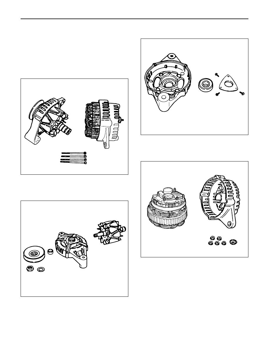
DISASSEMBLY

1. Remove the through bolt.

Insert the tip of a pry bar into the gaps between the
front cover and the stator core.
Pry apart and separate the front cover, rotor, the
rear cover and stator.

NOTE: Take care not to scratch or otherwise damage
the stator coil with pry bar.

2. Clamp the rotor in a vise and then remove the nut

and pulley.

3. Remove the rotor assembly from front cover.

4. Remove screws with bearing retainer from front

cover and remove bearing.

5. Remove the mounting nuts holding the “B ”

terminal, the diode, and the brush holder.

6. Separate the rear cover from the stator.

F06RT021

F06RT022

F06RT023

F06RT024

ENGINE ELECTRICAL 6D – 19

7. Remove bolts which secure stator terminal to

rectifier terminal, and remove stator.

8. Remove Bolts which secure regulator, rectifier and

brush-holder, and separate these parts.

NOTE: Do not apply a shock or load to regulator,
rectifier and brush holder.

INSPECTION AND REPAIR

Repair or replace necessary parts if extreme wear or
damage is found during inspection.

Rotor Assembly

1. Check the face of the slip rings for contamination

and roughness. If found to be scored, dress with a
fine sandpaper (#500 – 600). If found to be
contaminated, clean with a cloth saturated with
alcohol.

2. Measure the outside diameter of the slip rings.

Standard: 27 mm (1.06 in)
Limit: 26 mm (1.02 in)

3. Check resistance between slip rings, and replace if

there is no continuity.

Standard: 3.75 

or less

066RS030

066RW025

066RS032

066RS033

6D – 20 ENGINE ELECTRICAL

4. Check for continuity between slip ring and rotor

core.
In case of continuity, replace the rotor assembly.

Stator Coil

1. Check for continuity across the stator coils. If no

continuity exists, replace the coils.
Resistance value at 20°C

Standard: Approx 0.07

2. Check for continuity across one of the stator coils

and stator core. If a continuity exists, replace the
coil.

Standard: More than 1M

Brush

Measure the brush length.
If more than limit, replace the brush.

Standard: 18.0 mm (0.709 in)
Limit: 5.5 mm (0.217 in)

066RS017

066RS035

066RW024

066RS034

ENGINE ELECTRICAL 6D – 21

Rectifier Assembly

1. Measure the resistance between each diode

terminal and aluminum diode fin in forward and
reverse directions with the connection of the tester
leads switched. The diodes are normal if resistance
is nearly zero ohms in one direction and is infinitely
high in the other direction.

2. If a diode has no resistance or equal resistance in

both directions, it is defective and should be
replaced together with the holder.

IC Regulator Assembly

Connect a variable resistor, two 12V batteries, a fixed
resistor, and a voltmeter to the IC regulator as shown in
illustration.
a. Measuring equipment specifications

1. Fixed resistor (R1) : 10 Ohms / 3W
2. Variable resistor (Rv) : 0 – 300 Ohms / 12W
3. Batteries (BAT1, BAT2) : 12V (2 Batteries)
4. DC voltmeter : 0 – 50V / 0.5 steps (4 Check points)

b. Measuring procedure

1. Measure the voltage “V1” across the first battery

(BAT1). If the reading is between 10 and 13 volts,
the battery is normal.

2. Measure the voltage “V3” across both the batteries

(BAT1, BAT2). If the reading is between 20 and 26
bolts, the batteries are normal.

3. Gradually increase the resistance of the variable

resistor from zero. Measure the voltage “V2” (the
voltage across the F and E terminals).
Check to see that the voltage across “V1” changes
at this time. If there is no change, the voltage
regulator is faulty and must be replaced.

4. Measure the voltage at “V4” (the voltage across the

variable resistor center tap and terminal E with the
variable resistor resistance held constant). The
measure voltage should be within the specified
(14.4 ± 0.3 volts) limits. If it is not, the regulator
must be replaced.

Reassembly

To reassemble, follow the disassembly steps in the
reverse order, noting the following points:

NOTE:

1) Never make battery connections with polarities

reversed, or battery will be shorted via the diodes.
This will cause damage to the diodes.

2) Do not connect generator B terminal to ground; it is

connected directly to the battery.
This cable will burn if it is connected to ground.

3) Make sure to disconnect the positive (+) terminal of

the battery when quick-charging battery.
Diodes may be damaged due to abnormal pulse
voltage generated by the quick charger.

4) When reassembling the front section to rear

section, insert a stiff wire into hole in the rear face
of the rear cover from the outboard side to support
the brush in raised position, then insert the front
section to which rotor is assembled.

5) Reassemble parts carefully to be sure they fit into

their original position, paying attention to the
insulated portions.

6) Wipe insulating tubes, washers and plates clean

and install them in position carefully to avoid getting
oil or grease on them.

066RS036

R

E

B

S

R1

RV

BAT2

BAT1

V2

V3

V4

V1

066RW029


Content   ..  584  585  586  587   ..