Isuzu Trooper (1998-2002 year). Manual - part 584


  Index      Isuzu     Isuzu Trooper - service repair manual 1998-2002 year


Search            


Content   ..  582  583  584  585   ..


Isuzu Trooper (1998-2002 year). Manual - part 584


6D – 10 ENGINE ELECTRICAL

INSPECTION AND REPAIR

Repair or replace necessary parts if extreme wear or
damage is found during inspection.

Armature

1) Measure the outer diameter of commutator, and

replace with a new one if it is out of the limit.

Standard: 38.0 mm (1.50 in)
Limit: 36.5 mm (1.44 in)

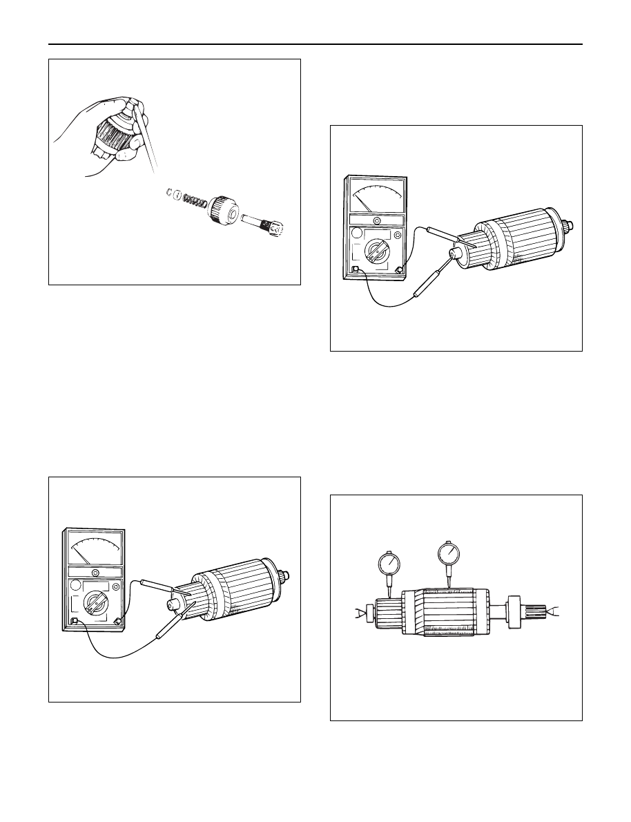
2) Check for continuity between commutator and

segments. Replace commutator if there is no
continuity (i.e., disconnected).

3) Check for continuity between commutator and

shaft. Also, check for continuity between
commutator and armature core, armature core and
shaft. Replace commutator if there is continuity
(i.e., internally grounded).

4) Measure runout of armature core and commutator

with a dial gage. Repair or replace, if it exceeds the
limit.

Armature

Standard: 0.05 mm (0.002 in) Max.
Limit: 0.1 mm (0.004 in)

Commutator

Standard: 0.05 mm (0.002 in) Max.
Limit: 0.1 mm (0.004 in)

065RW041

065RS015

065RS016

045RW045

ENGINE ELECTRICAL 6D – 11

5) Polish the commutator surface with sand paper

#500 to #600 if it is rough.

6) Measure the depth of insulator in commutator.

Repair, if it is below the limit.

Standard: 0.5 – 0.8 mm (0.02 – 0.03 in)

Limit: 0.2 mm (0.008 in)

Legend

(1) Steel Saw
(2) Chamfer
(3) Correct Condition
(4) Depth of Insulator
(5) Incorrect Condition
(6) Insulator
(7) Commutator Segment

Brush

1) Measure the length of brush.

Replace with a new one, if it is below the limit.

Standard: 18.0 mm (0.71 in)

Limit: 11.0 mm (0.43 in)

Brush holder

1) Check for continuity between brush holder (+) and

base (–). Replace, if there is continuity (i.e.,
insulation is broken).

065RW105

1

6

5

3

4

2

7

065RW102

065RW103

065RW104

6D – 12 ENGINE ELECTRICAL

2) Inspect the brush springs for wear, damage or other

abnormal conditions.

Standard: 28 – 35 N (2.9 – 3.6 kg/6.4 – 7.9 lb)

Magnetic switch

1) Continuity of shunt coil

Check for continuity between terminals S and coil
case.
Replace, if there is not continuity (i.e., coil is
disconnected.)

2) Continuity of series coil

Check for continuity between terminals S and M.
Replace, if there is no continuity (i.e., coil is
disconnected).

3) Continuity of contacts

With the plunger faced downward, push down the
magnetic switch. In this state, check for continuity
between terminals B and M. Replace, if there is no
continuity (i.e., contacts are faulty).

065RW052

065RW017

065RW018

065RW016

ENGINE ELECTRICAL 6D – 13

Pinion

1) Check by hand to see if the pinion rotates smoothly

in the dirve direction, or if it is locked when it is
rotated reversely.
If not, replace the pinion. 

Yoke assembly

1) Check the magnet inside the yoke.

Replace the yoke assembly if it is broken. 

REASSEMBLY

To install, follow the removal steps in the reverse order,
noting the following points:

Grease application places

1) Gears in reduction gear
2) Shift lever operating portion
3) Sliding potion of pinion
4) Plunger sliding portion of magnetic switch 

Pinion jump-out dimension

1) Connect the (+) cable of battery to terminal S and

the (–) cable to terminal M. Turn the switch on, and
measure pinion travel dimension “L” in thrust
direction from the jump-out position.

In measuring the dimension, pull the pinion out a little in
the arrow direction.

Dimension L: 0.3 – 1.5 mm (0.01 – 0.06 in)

If the measured value is out of standard, adjust the of
shims.

Legend

(1) Shim

065RW048

S

+

L

M

065RW054

1

065RW053


Content   ..  582  583  584  585   ..