Isuzu Trooper (1998-2002 year). Manual - part 580


  Index      Isuzu     Isuzu Trooper - service repair manual 1998-2002 year


Search            


Content   ..  578  579  580  581   ..


Isuzu Trooper (1998-2002 year). Manual - part 580


6C – 16 ENGINE FUEL

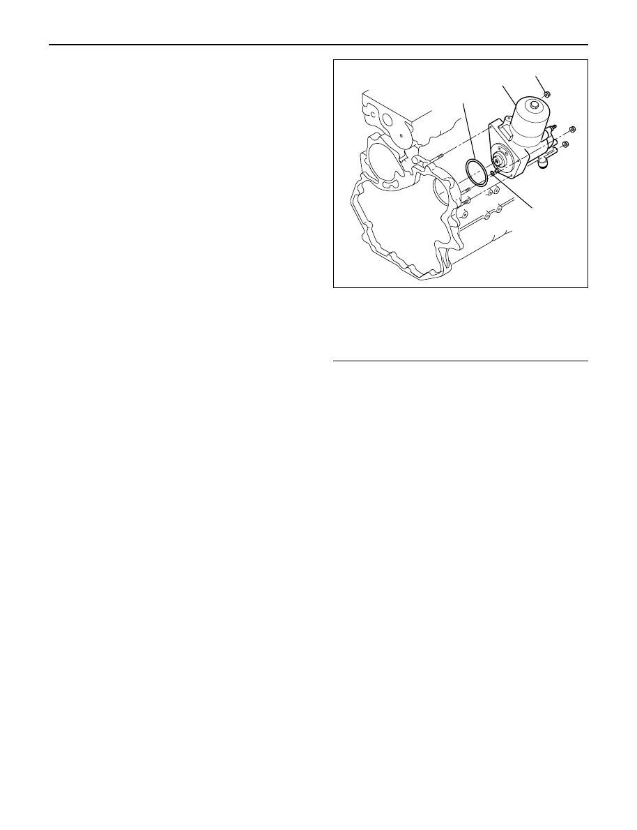
12. Remove high pressure oil pump
13. Remove high pressure oil pump assembly

Legend

(1) O-ring
(2) High pressure oil pump
(3) Nut
(4) O-ring

1

2

4

3

040RW007

ENGINE FUEL 6C – 17

INSPECTION AND REPAIR

The high pressure oil pump is made precisely,
therefore, disassembly is not recommended.

INSTALLATION

1. Set O-ring to high pressure oil pump assembly.

Apply Loctite No. 262 to the stud bolts.
Install the pump assembly into the rear of timing
gear case.
Tighten nut to specified torque.

Torque: 20 N·m (2.0 kg·m/14 lb ft)

Legend

(1) O-ring
(2) High Pressure Oil Pump Assembly
(3) Nuts
(4) O-ring

2. Tighten high pressure oil pump assembly bracket

together with two way valve bracket.

Torque: 27 N·m (2.8 kg·m/20 lb ft)

Legend

(1) High Pressure Oil Pump Assembly
(2) Nut
(3) Two Way Valve Bracket
(4) Bolt

3. Install the pump gear to align timing mark with idle

gear A.
Tighten high pressure pump gear fixing bolt to the
specified torque.
Apply engine oil to thread and seat of bolt.

Torque: 75 N·m (7.6 kg·m/55 lb ft)

Legend

(1) O-ring
(2) Pump Gear
(3) Bolt
(4) Timing Mark

1

2

4

3

040RW007

2

3

4

1

040RW006

4

GEAR:O/PUMP

IDLE GEAR A

1

2

3

040RW005

6C – 18 ENGINE FUEL

4. Remove lock bolt of idle gear A.
5. Install timing gear case cover.

Refer to “Timing gear” in this manual.

6. Install front plate.

Torque: 20 N·m (2.0 kg·m/14 lb ft)

7. Install timing pulley of high pressure oil pump.

Torque: 10 N·m (1.0 kg·m/87 lb in)

8. Install timing belt and tighten timing belt tensioner

assembly.
Refer to “Cylinder head” in this manual.

Legend

(1) Align Mark
(2) Camshaft Pulley
(3) Timing Belt
(4) High Pressure Oil Pump Pulley
(5) Tensioner Bolt B
(6) Tensioner Assembly
(7) Tensioner Bolt A
(8) Tensioner Spring

9. Install CMP sensor bracket.

Torque: 20 N·m (2.0 kg·m/14 lb ft)
10. Connect CMP sensor cable.
11. Install timing belt cover.

Torque: 9 N·m (0.9 kg·m/78 lb in)
12. Fill with about 300 cc of engine oil from the high

pressure oil pipe installation port of the oil rail using
an oil filler.
If assembled without filling the oil rail with oil, the
time for engine starting will be longer.

13. Immediately install high pressure oil pipe and

tighten to specified torque.

NOTE:

1) Use new O-ring.
2) Clean O-ring groove and fitting surface of parts.
3) Apply engine oil to O-ring.

Torque: 78 N·m (8.0 kg·m/58 lb ft)

14. Install the crankshaft damper pulley with specified

torque.

Torque: 216 N·m (22 kg·m/159 lb ft)
15. Install the intercooler assembly.

Refer to “Intercooler” in this manual.

16. Install air cleaner cover and air duct.

1

2

3

8

6

7

4

5

F06R200006

ENGINE FUEL 6C – 19

HIGH PRESSURE OIL PIPE INSTALLATION

1. Install upper bracket to two way valve, tighten them

temporarily.

2. Install pipe A to two way valve, tighten pipe A

temporarily with union nut D.

3. Install two way valve assembly to cylinder block,

tighgten with union nut C temporarily.

4. Install pipe B to two way valve, tighten union nut E

and union nut F temporarily.

5. Tighten upper bracket to specified torque.

Torque : 20 N·m (2.0 kg·m/14 lb ft)

6. Tighten union nut in the following order, union nut

C, D, F, and E to the specified torque.

Torque : 78 N·m (8.0 kg·m/58 lb ft)

7. Tighten lower bracket to the specified torque.

Torque : 20 N·m (2.0 kg·m/14 lb ft)

NOTE: Wash inside pipe, inside union nut and O-ring
seal surface to remove engine oil and foreign materials.

6

5

7

9

8

11

4

1

2

3

10

Legend

(1)

Union Nut F

(2)

Pipe B

(3)

Union Nut E

(4)

Upper Bracket

(5)

Two Way Valve

(6)

Union Nut D

(7)

Pipe A

(8)

Union Nut C

(9)

Lower Bracket

(10)

To Oil Rail

(11)

To High Pressure Oil Pump

052R200001


Content   ..  578  579  580  581   ..