Isuzu Trooper (1998-2002 year). Manual - part 570


  Index      Isuzu     Isuzu Trooper - service repair manual 1998-2002 year


Search            


Content   ..  568  569  570  571   ..


Isuzu Trooper (1998-2002 year). Manual - part 570


6A – 88 ENGINE MECHANICAL

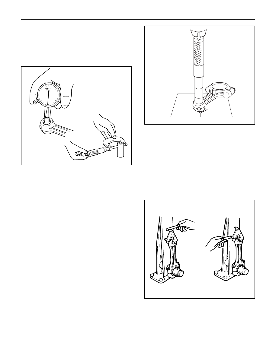
2. Measure the inside diameter of the connecting rod

small end. If the clearance between the small end
and pin does not conform to the specified value, the
connecting rod or bushing and pin must be
replaced.

Standard: 0.008 – 0.020 mm (0.0003 – 0.0008 in )
Limit: 0.05 mm (0.0020 in)

3. Insert the piston pin into the piston and rotate it. If

the pin rotates smoothly with no backlash, the
clearance is normal. If there is backlash or
roughness, measure the clearance. If the clearance
exceeds the specified limit, the piston and the
piston pin must be replaced.

Standard: 0.005 – 0.018 mm (0.0002 – 0.0007 in )
Limit: 0.04 mm (0.0016 in)

Bushing replacement

Removal:

Use a suitable bar and bench press or
hammer

Installation:

Align the bushing with a connecting rod
oil port. After installing a new bushing,
finish the bushing bore with a pin hole
grinder.

Connecting rods

1. Check the connecting rod alignment with a

connecting rod aligner.
If either the bend or the twist exceeds the specified
limit, the connecting rod must be replaced.

Bend per 100 mm (3.937 in)
Standard: 0.08 mm (0.0031 in) or less
Limit: 0.20 mm (0.0079 in)

Twist per 100 mm (3.937 in)
Standard: 0.05 mm (0.0020 in) or less
Limit: 0.15 mm (0.0059 in)

2. Measure the connecting rod thrust clearance.

Use a feeler gauge to measure the thrust clearance
at the big end of the connecting rod.

If the clearance exceeds the specified limit, the
connecting rod must be replaced.

Standard: 0.230 mm (0.0091 in)
Limit: 0.350 mm (0.0138 in)

012RW074

012RW123

012RW001

ENGINE MECHANICAL 6A – 89

3. Measure the oil clearance between the connecting

rod and the crankshaft.
1) Remove the connecting rod cap nuts and the

rod caps.
Arrange the removed rod caps in the cylinder
number order.

2) Clean the rod bearings and the crankshaft pins.
3) Carefully check the rod bearings.

If even one bearing is found to be damaged or
badly worn, the entire bearing assembly must be
replaced as a set. Reinstall the bearings in their
original positions.
Apply plastigage to the crank pin.

4) Reinstall the rod caps to their original positions.

5) Tighten the cap nuts in 2 steps, using angular

tightening method as shown in the following
specifications.

1st step: 29 N·m (3.0 kg·m/22 lb ft)
2nd step: 45°– 60°

NOTE: Do not allow the crankshaft to rotate

6) Remove the rod caps.
7) Measure the smallest width of the plastigage

and determine the oil clearance. If the oil
clearance exceeds the limit, replace the rod
bearings as a set.

8) Clean the plastigage from the bearings and the

crankshaft pins

Standard: 0.022 – 0.042 mm (0.0009 – 0.0017 in)
Limit: 0.100 mm (0.0039 in)

REASSEMBLY

1. Connecting Rod
2. Piston
3. Piston Pin

1) Apply a coat of engine oil to the piston pin and

the piston pin hole.

4. Piston Pin Snap Ring

1) Try to insert the piston pin into the piston pin

hole with normal finger pressure.

2) Weight each piston and connecting rod

assembly.

3) Select piston and connecting rod combinations

so that the weight variation of the different four
assemblies is held within the specified limits.

Variance in weight after assembly: Less than 3g
(0.1058 oz)

NOTE: When changing piston/connecting rod
combinations, do not change the piston/piston pin
combination.

4) Attach the piston to the connecting rod with the

piston front mark (2) and the connecting rod
front mark (3) on the same side.

014RW055

012RW075

014RW077

6A – 90 ENGINE MECHANICAL

5. Piston Ring

1) Install the piston rings with the piston ring

expander.
The compression ring must be set with the 1N,
2N mark facing up.

2) Discerning mark is stamped as shown in the

illustration (1).

Marked 1N: 1st compression ring

Marked 2N: 2nd compression ring

3) Install piston rings in the following sequence.

1) Oil ring

(1) After installing the expander ring then assemble

the oil ring.

2) 2nd compression ring

3) 1st compression ring

1) The compression ring must be set with the 1N or

2N mark facing up.

2) 1st compression ring:1N
3) 2nd compression ring: 2N
4) After installation, apply engine oil to the entire

circumference of the piston rings.
Check to see that all the rings rotate smoothly.

5) Insert the bearings into the connecting rods and

caps.
Apply new engine oil to the bearing faces.
Cap side bearings have no oil hole.
Connecting rod side bearing’s oil hole should be
aligned with oil hole on the connecting rod.

6. Piston and Connecting Rod

1) Apply engine oil to the cylinder bores, the

connecting rod bearings and the crankshaft
pins.

2) Check to see that the piston ring end gaps are

correctly positioned.

N

012RW037

2

3

1

015RW051

3

2

1

1

012RW058

ENGINE MECHANICAL 6A – 91

Legend

(1) 1st compressor ring gap
(2) 2nd compressor ring gap
(3) Oil ring gap

3) Insert the piston/connecting rod assemblies into

each cylinder with the piston ring compressor.

4) The front marks must be facing the front of the

engine.

Piston Ring Compressor : 5-8840-9018-0

7. Connecting Rod Bearing Cap

1) Apply engine oil to thread and seat of bearing

cap bolts.

2) Tighten the cap bolts in 2 steps, using angular

tightening method as shown in the following
specifications.

1st step: 29 N·m (3.0 kg·m/22 lb ft)
2nd step: 45°– 60°

After tightening the cap bolts, check to see that
the crankshaft rotates smoothly.

8. Crank Case Assembly

1) Refer to “Crank Case” in this manual.

9. Cylinder Head Assembly

1) Refer to “Cylinder head” in this manual.

3

1

2

015RW083


Content   ..  568  569  570  571   ..