Isuzu Trooper (1998-2002 year). Manual - part 518
6E–442
6VE1 3.5 ENGINE DRIVEABILITY AND EMISSIONS
Diagnostic Trouble Code (DTC)
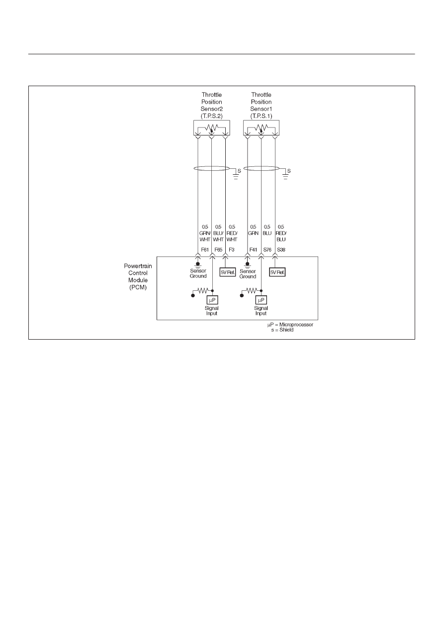
P1635 Reference Voltage # 1 Circuit Fault
D06RY00077
Circuit Description
The TP sensor # 1 shares a 5 Volt reference with the
PCM.
If the PCM detects the 5 Volt reference for the TP sensor #
1 is failure, DTCP1635 will be set.
Conditions for setting the DTC
D
The ignition is “ON”.
D
The 5 Volt reference voltage for the TP sensor # 1 is
less than 4 volts.
D
The 5 Volt reference voltage for the TP sensor # 1 is
more than 5 volts.
Action Taken When the DTC Sets
D
The PCM will not illuminate the malfunction indicator
lamp (MIL) .
D
The PCM will store condition which were present when
the DTC was set as Freeze Frame and in the Failure
Records data.
Conditions for Clearing the MIL/DTC
D
The PCM will turn the MIL “OFF” on the third
consecutive trip cycle during which the diagnostic has
been run and the fault condtion is no longer present.
D
A history DTC P1635 will clear after 40 cosecutive trip
cycle during which the warm up cycles have occurred
without a fault.
D
DTC P1635 can be cleared using the Tech 2 “Clear
Info” function or by disconnecting the PCM battery
feed. Tech2 “ Clear Info” function or by disconnecting
the PCM battery feed.