Isuzu Trooper (1998-2002 year). Manual - part 470


  Index      Isuzu     Isuzu Trooper - service repair manual 1998-2002 year


Search            


Content   ..  468  469  470  471   ..


Isuzu Trooper (1998-2002 year). Manual - part 470


6E–250

6VE1 3.5 ENGINE DRIVEABILITY AND EMISSIONS

Diagnostic Trouble Code (DTC) 

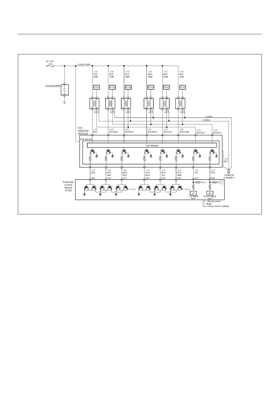
P0325  ION Sensing Module/ION Sensing Knock Intensity Circuit Fault

D06R200098

Circuit Description

The Power Control Module (PCM) checks the validity of
the signals used in the ION Sensing module at the
following engine operating conditions.

D

The test is performed to evacuate the Knock Intensity
(KI) signal pulse width if it is within a predetermined
range. If the KI signal pulse width is out of the
predetermined range, the fail counter will be
incremented. If the failure counter exceeds the
calibration, then test is complete and a failure will be
reported. If the sample counter threshold is reached
before the failure threshold, then the test is complete
and a pass will be reported. This test will detect an
open/short in the KI line circuit, ION module faults and
analog input faults in the PCM.

Conditions for setting the DTC

D

Ignition voltage is between 10volt and 16 volts.

D

No Crank DTCs set.

D

No EST DTCs set.

D

No Misfire DTCs set.

Action Taken When the DTC Sets

D

The PCM will ON the MIL after second trip with
detected the fault.

D

The PCM calculates an air flow value based on idle air
control valve position, throttle position, RPM and
barometric pressure.

D

The PCM will store condition which were present when
the DTC was set as Freeze Frame and in the Failure
Records data.

Conditions for Clearing the MIL/DTC

D

The PCM will turn the MIL “OFF” on the third
consecutive trip cycle during which the diagnostic has
been run and the fault condition is no longer present.

D

A history DTC P0325 will clear after 40 consecutive trip
cycles during which the warm up cycles have occurred
without a fault.

D

DTC P0325 can be cleared using the Tech2 “Clear
Info” function or by disconnecting the PCM battery
feed.

Diagnostic Aids

An intermittent may be caused by the following:

D

Poor connections.

D

Misrouted harness.

D

Rubbed through wire insulation.

D

Broken wire inside the insulation.

Check for the following conditions:

D

Poor connection at PCM- Inspect harness connectors
for backed out terminals, improper mating, broken
locks, improperly formed or damaged terminals, and
poor terminal to wire connection.

D

Damaged harness-Inspect the wiring harness for
damage.

6E–251

6VE1 3.5L ENGINE DRIVEABILITY AND EMISSIONS

If the harness appears to be OK, observe the Knock
Present, Knock Sensor Noise Channel display on
the Tech 2 while moving connectors and wiring
harnesses related to the sensor.

A change in the display will indicate the location of
the fault.

If DTC P0325 cannot be duplicated, the information
included in the Failure Records data can be useful in
determined vehicle mileage since the DTC was last
set.

If it is determined that the DTC occurs intermittently,
performing the DTC P0325 Diagnostic Chart may
isolate the cause of the fault.

DTC P0325 - ION Sensing Module Knock Intensity Circuit Fault


Step

Action

Value(s)

Yes

No

1

Was the “On-Board (OBD) System Check” performed?

Go to 

Step 2

Go to 

OBD

System

Check

2

1. Ignition “ON”, engine “OFF”.
2. Review and record Tech 2 Failure Records data.
3. Operate the vehicle within Failure Records

conditions as noted.

4.  Using a Tech 2, monitor “DTC” info for DTC P0325.

Does the Tech 2 indicate DTC P0325 failed this
ignition?

Go to 

Step 3

Check the

Procedure

Refer to

Diagnostic

Aids

3

1. Ignition  “OFF”.
2. Disconnect the ION sensing module.
3. Disconnect the PCM.

Is the action complete?

Go to 

Step 4

4

Check the ION sensing harness between the PCM
(F68) and ION sensing module circuit (RED Wire) at
the KI line harness connector.

Was a problem found?

Verify repair

Go to 

Step 5

5

1. Disconnect the ignition coil.

Is the action complete?

Go to 

Step 6

6

Check the ION sensing harness for open or short circuit
between the ignition coil and ION sensing module
circuit at the harness connector.

Was a problem found?

Verify repair

Go to 

Step 7

7

Check the following items;

1. Ignition coil and ignition coil circuit.
2. Ignition coil ground circuit for a poor connection.
3. If a problem is found, repair wiring harness as

necessary.

Was a problem found?

Verify repair

Go to 

Step 8

8

Replace the Ignition coil.

Is the action complete?

Verify repair

Go to 

Step 9

9

Check the following items;

1. ION sensing module ground circuit for a poor

connection.

2. If a problem is found, repair wiring harness as

necessary.

Was a problem found?

Go to 

Step 10

Go to 

Step 11

10

Repair wiring harness.

Is the action complete?

Verify repair

Go to 

Step 11

6E–252

6VE1 3.5 ENGINE DRIVEABILITY AND EMISSIONS

DTC P0325 - ION Sensing Module Knock Intensity Circuit Fault

  (Cont'd)

Step

No

Yes

Value(s)

Action

11

Replace the ION Sensing module.

Is the action complete?

Verify repair

Go to 

Step 12

12

Replace the PCM.

IMPORTANT: The replacement PCM must be
programmed. 
Refer to 

ON-Vehicle Service in Power Control Module

and Sensors for procedures.
And also refer to latest Service Bulletin. Check to see if
the latest software is released or not .And then Down
Load the LATEST PROGRAMMED SOFTWARE to
the replacement PCM.

Is the action complete?

Verify repair

6E–253

6VE1 3.5L ENGINE DRIVEABILITY AND EMISSIONS

Diagnostic Trouble Code (DTC) 

P0336 58X Reference Signal Circuit

D06R200044

Circuit Description

The 58X reference signal is produced by the crankshaft
position (CKP) sensor.  During one crankshaft revolution,
58 crankshaft pulses will be produced.  The powertrain
control module (PCM) uses the 58X reference signal to
calculate engine RPM and crankshaft position.  The PCM
constantly monitors the number of pulses on the 58X
reference circuit.  If the PCM receives an incorrect
number of pulses on the 58X reference circuit, DTC
P0336 will set.

Conditions for Setting the DTC

D

Engine is running.

D

Extra or missing pulse is detected between
consecutive 58X reference pulses.

D

Above condition is detected in 10 of 100 crankshaft
rotations.

Action Taken When the DTC Sets

D

The PCM will illuminate the malfunction indicator lamp
(MIL) after the second consecutive trip in which the
fault is detected.

D

The PCM will store conditions which were present
when the DTC was set as Freeze Frame and in the
Failure Records data.

Conditions for Clearing the MIL/DTC

D

The PCM will turn the MIL “OFF” on the third
consecutive trip cycle during which the diagnostic has
been run and the fault condition is no longer present.

D

A history DTC P0336 will clear after 40 consecutive
warm–up cycles have occurred without a fault.

D

DTC P0336 can be cleared by using the Tech 2 “Clear
Info” function or by disconnecting the PCM battery
feed.


Content   ..  468  469  470  471   ..