Isuzu Trooper (1998-2002 year). Manual - part 425
6E–70
6VE1 3.5 ENGINE DRIVEABILITY AND EMISSIONS
Electronic Ignition System Diagnosis
If the engine cranks but will not run or immediately stalls,
the Engine Cranks But Will Not Start chart must be used
to determine if the failure is in the ignition system or the
fuel system. If DTC P0300 through P0306, P0341, or
P0336 is set, the appropriate diagnostic trouble code
chart must be used for diagnosis.
If a misfire is being experienced with no DTC set, refer to
the
Symptoms section for diagnosis.
Visual Check of The Evaporative
Emission Canister
D
If the canister is cracked or damaged, replace the
canister.
D
If fuel is leaking from the canister, replace the canister
and check hoses and hose routing.
Fuel Metering System Check
Some failures of the fuel metering system will result in an
“Engine Cranks But Will Not Run” symptom. If this
condition exists, refer to the
Cranks But Will Not Run
chart. This chart will determine if the problem is caused
by the ignition system, the PCM, or the fuel pump
electrical circuit.
Refer to
Fuel System Electrical Test for the fuel system
wiring schematic.
If there is a fuel delivery problem, refer to
Fuel System
Diagnosis, which diagnoses the fuel injectors, the fuel
pressure regulator, and the fuel pump. If a malfunction
occurs in the fuel metering system, it usually results in
either a rich HO2S signal or a lean HO2S signal. This
condition is indicated by the HO2S voltage, which causes
the PCM to change the fuel calculation (fuel injector pulse
width) based on the HO2S reading. Changes made to the
fuel calculation will be indicated by a change in the long
term fuel trim values which can be monitored with a
Tech 2. Ideal long term fuel trim values are around 0%;
for a lean HO2S signal, the PCM will add fuel, resulting in
a fuel trim value above 0%. Some variations in fuel trim
values are normal because all engines are not exactly the
same. If the evaporative emission canister purge is “ON”,
the fuel trim may be as low as –38%. If the fuel trim values
are greater than +23%, refer to
DTC P0131, DTC P0151,
DTC P0171, and DTC 1171 for items which can cause a
lean HO2S signal.
Fuel System Pressure Test
A fuel system pressure test is part of several of the
diagnostic charts and symptom checks. To perform this
test, refer to
Fuel Systems Diagnosis.
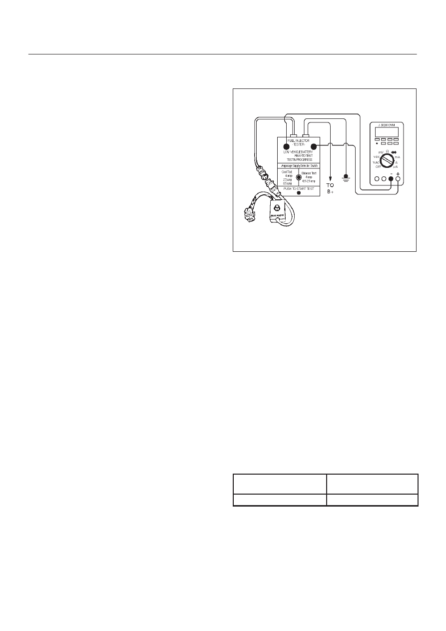
Fuel Injector Coil Test Procedure and
Fuel Injector Balance Test Procedure
T32003
Test Description
Number(s) below refer to the step number(s) on the
Diagnostic Chart:
2. Relieve the fuel pressure by connecting the J
34730-1 Fuel Pressure Gauge to the fuel pressure
connection on the fuel rail.
CAUTION: In order to reduce the risk of fire and
personal injury, wrap a shop towel around the fuel
pressure connection. The towel will absorb any fuel
leakage that occurs during the connection of the fuel
pressure gauge. Place the towel in an approved
container when the connection of the fuel pressure
gauge is complete.
Place the fuel pressure gauge bleed hose in an
approved gasoline container.
With the ignition switch “OFF”, open the valve on the
fuel pressure gauge.
3. Record the lowest voltage displayed by the DVM
after the first second of the test. (During the first
second, voltage displayed by the DVM may be
inaccurate due to the initial current surge.)
Injector Specifications:
Resistance (Ohms)
Voltage Specification at
10
°
C-35
°
C (50
°
F-95
°
F)
11.8 – 12.6
5.7 – 6.6