Isuzu Trooper (1998-2002 year). Manual - part 423
6E–62
6VE1 3.5 ENGINE DRIVEABILITY AND EMISSIONS
On-Board Diagnostic (OBD) System Check
D06RY00053
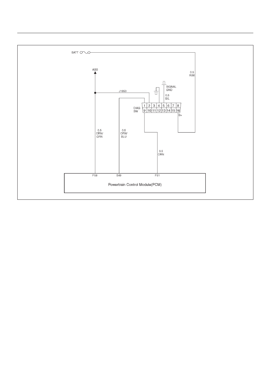
Circuit Description
The on-board diagnostic system check is the starting
point for any driveability complaint diagnosis. Before
using this procedure, perform a careful visual/physical
check of the PCM and engine grounds for cleanliness and
tightness.
The on-board diagnostic system check is an organized
approach to identifying a problem created by an
electronic engine control system malfunction.
Diagnostic Aids
An intermittent may be caused by a poor connection,
rubbed–through wire insulation or a wire broken inside the
insulation. Check for poor connections or a damaged
harness. Inspect the PCM harness and connector for
improper mating, broken locks, improperly formed or
damaged terminals, poor terminal-to-wire connection,
and damaged harness.
Test Description
Number(s) below refer to the step number(s) on the
Diagnostic Chart:
2. The MIL (“Check Engine lamp”) should be “ON”
steady with the ignition “ON ” and the engine “OFF”.
If not, the “No MIL” chart should be used to isolate
the malfunction.
3. The SVS (“Service Vehicle Soon”) lamp should be
“ON” steady with the ignition “ON ”and the engine
“OFF”. If not, the “No SVS lamp”chart should be
used to isolate the malfunction.
4. Checks the Class 2 data circuit and ensures that the
PCM is able to transmit serial data.
5. This test ensures that the PCM is capable of
controlling the MIL (“Check Engine lamp”) and the
MIL (“Check Engine lamp”) driver circuit is not
shorted to ground.
6. This test ensures that the PCM is capable of
controlling the SVS (“Service Vehicle Soon”) lamp
and the SVS (“Service Vehicle Soon”) lamp driver
circuit is not shorted to ground.
8. Check the DTCs (System ,Volts Supply circuit).
9. Check the DTCs (PCM{Software} detect Errors).
12.If the engine will not start, the Cranks But Will Not
Run chart should be used to diagnose the condition.
15.A Tech 2 parameter which is not within the typical
range may help to isolate the area which is causing
the problem.
16.This vehicle is equipped with a PCM which utilizes
an electrically erasable programmable read only
memory (EEPROM). When the PCM is replaced,
the new PCM must be programmed. Refer to
PCM
Replacement and Programming Procedures in
Powertrain Control Module (PCM) and Sensors of
this section.
11.If the starter motor will not start, the starter control
system chart should be used to diagnose the
condition.