Isuzu Trooper (1998-2002 year). Manual - part 243
6A–46
ENGINE MECHANICAL
D
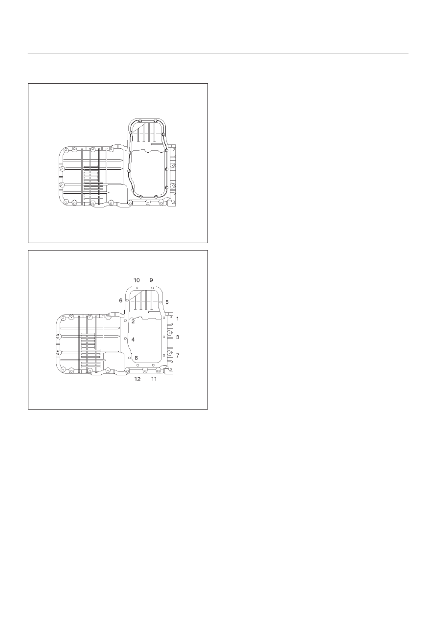
Tighten fixing bolts to the specified torque.
Torque : 25 N·m (2.5 Kg·m/18 lb ft)
013RW003
013RW002
13. Install timing belt.
D
Refer to installation procedure for Timing Belt in this
manual.
14. Install engine assembly.
D
Refer to installation procedure for Engine in this
manual.