Isuzu Trooper (1998-2002 year). Manual - part 171


  Index      Isuzu     Isuzu Trooper - service repair manual 1998-2002 year


Search            


Content   ..  169  170  171  172   ..


Isuzu Trooper (1998-2002 year). Manual - part 171


4C–48

DRIVE SHAFT SYSTEM

Rear Propeller Shaft

General Description

Since the propeller shaft is balanced carefully, welding or
any other modifications are not permitted.

Alignment marks should be applied to each propeller
shaft before removal.

401RW003

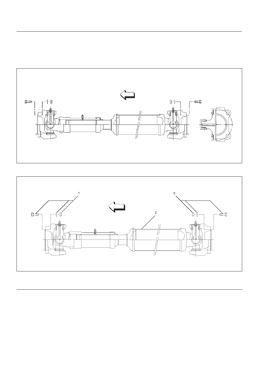
Rear Propeller Shaft and Associated Parts

401RW059

Legend

(1) Bolt, Nut and Washer

(2) Rear Propeller Shaft
(3) Bolt, Nut and Washer

4C–49

DRIVE SHAFT SYSTEM

Removal

1. Jack up the vehicle and support it on the chassis

stands.

2. Gear shift lever should be placed in neutral position

and parking brake released.

NOTE: Apply alignment marks on the flange at the rear
propeller shaft both front and rear side.

401RS023

3. Remove bolt, nut and washer (Rear axle side).
4. Remove bolt, nut and washer (Transfer side).
5. Remove rear propeller shaft.

Installation

NOTE: Never install the shaft assembly backwards.

1. Completely remove the black paint from the

connecting surface of flange coupling on each end of
propeller shaft. Clean so that no foreign matter will be
caught in between.

2. Align the mark which is applied at removal .

Install rear propeller shaft and tighten the bolts to the
specified torque.

Torque: 63 N·m  (6.4 kg·m/46 lb ft)

3. After installing the propeller shaft, be sure to apply

black paint (1) to exposed area (other than
connecting surface) of the entire surface of flange
coupling .

401RS022

4C–50

DRIVE SHAFT SYSTEM

Disassembly

401RW057

Legend

(1) Sleeve Yoke

(2) Seal
(3) Tube Assembly

1. Apply alignment marks (1) on the sleeve yoke and

tube assembly then remove sleeve yoke.

401RW056

2. Remove seal.
3. Remove tube assembly.

4C–51

DRIVE SHAFT SYSTEM

Universal Joint Disassembly

401RW054

Legend

(1) Flange Yoke
(2) Spider with Grease Fitting

(3) Snap Ring
(4) Needle Roller Bearing
(5) Grease Fitting

1. Apply alignment marks (1) on the yokes of the

universal joint, then remove snap ring.

401RS028

2. Tap out the needle roller bearing by gently striking the

shoulder of the yoke, using a mallet or a copper
hammer.

401RS006


Content   ..  169  170  171  172   ..