Content .. 1103 1104 1105 1106 ..
Isuzu Trooper (1998-2002 year). Manual - part 1105
9J1–57
RESTRAINT CONTROL SYSTEM
DTC 44 Driver Pretensioner Loop Open
D09RW014
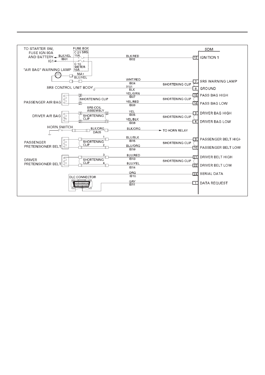
Circuit Description:
When the ignition switch is turned “ON”, the SDM will
perform tests to diagnose critical malfunctions within
itself. Upon passing these tests, “Ignition 1”, and
pretensioner loop voltages are measured to ensure they
are within their respective normal voltage ranges.
During “Continuous Monitoring” diagnostics, a fixed
amount of current is following in the pretensioner loop.
This produces proportional voltage drops in the loop. By
monitoring the voltage difference between “Driver Belt
High” and “Driver Belt Low”, the SDM calculates the
combined resistance of the driver pretensioner assembly,
harness wiring IB13–BLU/RED and IB14–BLU/YEL, and
connector terminal contact.
DTC Will Set When:
The voltage difference between “Driver Belt High”
terminal “21” and “Driver Belt Low” terminal “22” is above
or equal to a specified value for 500 milliseconds during
“Continuous Monitoring”.
Action Taken:
SDM turns “ON” the “AIR BAG” warning lamp and sets a
diagnostic trouble code.
DTC Will Clear When:
The voltage difference between “Driver Belt High”
terminal “21” and “Driver Belt Low” terminal “22” is below
a specified value for 500 milliseconds during “Continuous
Monitoring”.
DTC Chart Test Description:
Number(s) below refer to step number(s) on the
diagnostic chart:
2. This test determines whether the malfunction is in
the SDM.
3. This test verifies proper connection of the yellow
2–pin connector at the base of the driver seat.
4. This test checks for proper contact and/or corrosion
of the yellow 2–pin connector at the base of the
driver seat.
5. This test isolates the malfunction to one side of the
driver pretensioner assembly yellow 2–pin
connector located at the base of driver seat.
6. This test determines whether the open is in the
wiring.
Diagnostic Aids:
An intermittent condition is likely to be caused by a poor
connection at the driver pretensioner assembly harness
2–pin connector terminals “3” and “4” at the top of the
steering column, SDM terminals “21” and “22”, or an open
in IB13–BLU/RED and IB14–BLU/YEL.