Content .. 1100 1101 1102 1103 ..
Isuzu Trooper (1998-2002 year). Manual - part 1102
9J1–45
RESTRAINT CONTROL SYSTEM
DTC 31 Passenger Pretensioner Loop Resistance High
D09RW014
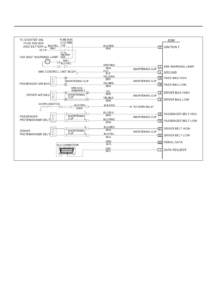
Circuit Description:
When the ignition switch is turned “ON”, the SDM will
perform tests to diagnose critical malfunctions within
itself. Upon passing these tests “Ignition 1”, and
deployment loop voltages are measured to ensure they
are within their respective normal voltage ranges. The
SDM then proceeds with the “Resistance Measurement
Test”. “Passenger Belt Low” terminal “10” is grounded
through a resister and the passenger current source
connected to “Passenger Belt High” terminal “9” allows a
known amount of current to flow. By monitoring the
voltage difference between “Passenger Belt High” and
“Passenger Belt Low” the SDM calculates the combined
resistance of the passenger air bag assembly, harness
wiring IB15–BLU/BLK and IB16–BLU/ORG connector
terminal contact.
DTC Will Set When:
The combined resistance of the passenger pretensioner
assembly, harness wiring IB15–BLU/BLK and
IB16–BLU/ORG, and connector terminal contact is
above a specified value. This test is run once each
ignition cycle during the “Resistance Measurement Test”
when:
1. No “higher priority faults” are detected during
“Turn–ON”,
2. “Ignition 1” voltage is in the specified value.
Action Taken:
SDM turns “ON” the “AIR BAG” warning lamp and sets a
diagnostic trouble code.
DTC Will Clear When:
The ignition switch is turned “OFF.”
DTC Chart Test Description:
Number(s) below refer to step number(s) on the
diagnostic chart:
2. This test determines whether the malfunction is in
the SDM.
3. This test verifies proper connection of the yellow
2–pin connector.
4. This test checks for proper contact and/or corrosion
of the yellow 2–pin connector terminals.
5. The test checks for a malfunctioning passenger
pretensioner assembly.
6. This test determines whether the malfunction is due
to high resistance in the wiring.
Diagnostic Aids:
An intermittent condition is likely to be caused by a poor
connection at the passenger air bag assembly harness
connector terminals “1” and “2”, SDM terminal “9” and
“10”, or a poor wire to terminal connection in
IB15–BLU/BLK and IB16–BLU/ORG. This test for this
diagnostic trouble code is only run while the “AIR BAG”