Content .. 1093 1094 1095 1096 ..
Isuzu Trooper (1998-2002 year). Manual - part 1095
9J1–17
RESTRAINT CONTROL SYSTEM
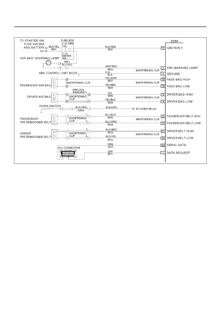
DTC 17 Passenger Deployment Loop Open
D09RW014
Circuit Description:
When the ignition switch is turned “ON”, the SDM will
perform tests to diagnose critical malfunctions within
itself. Upon passing these tests, “Ignition 1”, and
deployment loop voltages are measured to ensure they
are within their respective normal voltage ranges. During
“Continuous Monitoring” diagnostics, a fixed amount of
current is flowing in the deployment loop. This produces
proportional voltage drops in the loop. By monitoring the
voltage difference between “Passenger Bag High” and
“Passenger Bag Low”, the SDM calculates the combined
resistance of the passenger air bag assembly, harness
wiring IB07–YEL/GRN AND IB08–YEL/RED, and
connector terminal contact.
DTC Will Set When:
The voltage difference between “Passenger Bag High”
terminal “15” and “Passenger Bag Low” terminal “16” is
above or equal to a specified value for 500 milliseconds
during “Continuous Monitoring”.
Action Taken:
SDM turns “ON” the “AIR BAG” warning lamp and sets a
diagnostic trouble code.
DTC Will Clear When:
The voltage difference between “Passenger Bag High”
terminal “15” and “Passenger Bag Low” terminal “16” is
below a specified value for 500 milliseconds during
“Continuous Monitoring”.
DTC Chart Test Description:
Number(s) below refer to step number(s) on the
diagnostic chart:
2. This test determines whether the malfunction is in
the SDM.
3. This test verifies proper connection of the yellow
2–pin connector.
4. This test cheeks for proper contact and/or corrosion
of the shorting clip in the yellow 2–pin connector
terminals.
5. The test checks for a malfunctioning passenger air
bag assembly.
6. This test determines whether the open in the wiring.
Diagnostic Aids:
An intermittent condition is likely to be caused by a poor
connection at the passenger air bag assembly harness
connector terminals“2” and “3”, SDM terminals “15” and
“16”, or an open in IB07–YEL/GRN and IB08–YEL/RED.