Isuzu Trooper (1998-2002 year). Manual - part 1063


  Index      Isuzu     Isuzu Trooper - service repair manual 1998-2002 year


Search            


Content   ..  1061  1062  1063  1064   ..


Isuzu Trooper (1998-2002 year). Manual - part 1063


SUN ROOF/CONVERTIBLE TOP

8I–9

Sun Roof Drain Hose (Front Side)

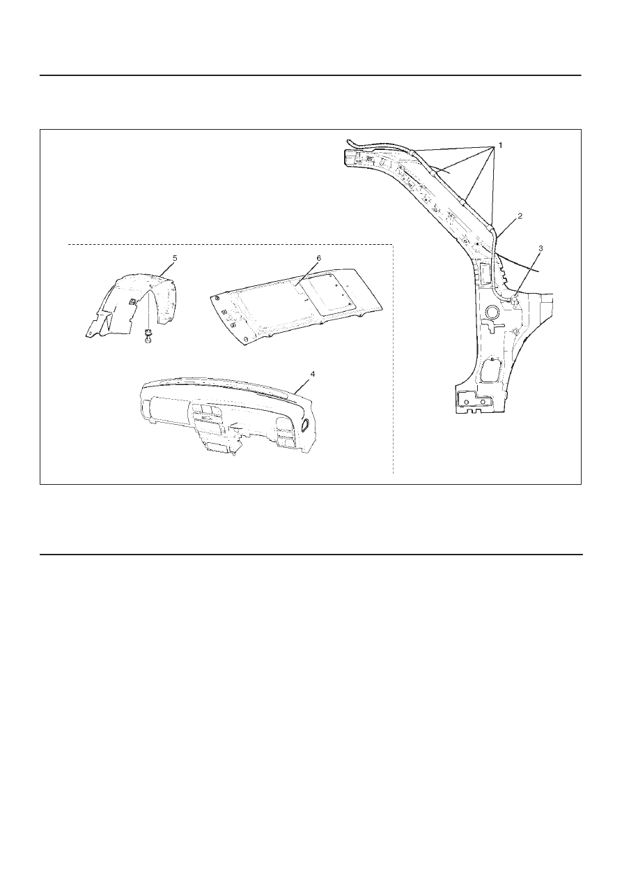
Sun Roof Drain Hose (Front Side) and Associated Parts

665RW017

Legend

(1) Clip
(2) Sun Roof Drain Hose
(3) Grommet

(4) Instrument Panel Assembly
(5) Front Inner Liner
(6) Headlining

Removal

1. Disconnect the battery ground cable.
2. Remove the front inner liner.
3. Remove the headlining.

D

Refer to the Headlining in Body Structure section.

4. Remove the instrument panel assembly.

D

Refer to the Instrument Panel Assembly in Body
Structure section.

5. Disconnect the drain hose at the frame complete

side.

6. Apply the soap and water to the body panel grommet.
7. Pass the string from the sun roof frame side through

the drain port side, and remove the drain hose from
the hose fixing clips.  Taking care not to allow the body
panel grommet to be removed together with the hose,
pull the drain hose only to the inside of the vehicle.
(The string should be kept as it is.)

Installation

To install, follow the removal steps in the reverse order,
noting the following points.

1. Apply the soap and water to the body panel grommet.
2. Install the drain hose from inside of the vehicle by

utilizing, as a guide, the string passed during removal
step.

3. The body panel grommet must not be twisted or

caught in during installation.

4. Complete routing, avoiding extreme bends or curves.
5. After routing, install the trim with care not to allow the

drain hose to be caught in.

6. Test the drain condition.
7. The protrusion of drain hose from the body panel

must be within 50 mm (2.0 in).  If it exceeds 50 mm
(2.0 in) after correct routing, cut the leading edge so
that the protrusion is within 50 mm (2.0 in).

8I–10

SUN ROOF/CONVERTIBLE TOP

Sun Roof Drain Hose (Rear Side)

Sun Roof Drain Hose (Rear Side) and Associated Parts

665RS015

Legend

(1) Soft Tape
(2) Pipe
(3) Clip
(4) Soft Tape
(5) Sun Roof Drain Hose

(6) Tape
(7) Grommet
(8) Grommet
(9) Clip

(10) Headlining

(11) Rear Fender Inner Liner

Removal

1. Disconnect the battery ground cable.
2. Remove the rear fender inner liner.
3. Remove the headlining.

D

Refer to the Headlining in Body Structure section.

4. Disconnect the drain hose at the frame complete

side.

5. Apply the soap and water to the body panel grommet.
6. Remove the hose fixing tapes and clips.
7. Pull the drain hose to the inside of the vehicle.

Installation

To install, follow the removal steps in the reverse order,
noting the following points.

1. Apply the soap and water to the body panel grommet.

SUN ROOF/CONVERTIBLE TOP

8I–11

2. Insert the drain hose from inside of vehicle, restore

routing, and fix with new soft tape and clip.
If the grommet is removed during removal of drain
hose, insert the grommet into drain hose from outside
of the vehicle, and install on the body panel, avoiding
any twisting.

3. After installing the drain hose, install the trim while

taking care not to crush the drain hose.
Also, care should be taken not to allow the drain hose
connected to the pipe to be caught in.

4. Test the drain condition.
5. The protrusion of the drain hose from the body panel

must be within 50 mm (2.0 in).  If it exceeds 50 mm
(2.0 in) after correct routing, cut the leading edge so
that the protrusion is within 50 mm (2.0 in).

Sun Roof Switch

General Description

Sun roof operation can be controlled by pushing
continuously the sun roof switch to activate the sun roof
control unit and sun roof motor.
While the switch is being pushed to the “OPEN” side, the
sun roof stops about 165 mm (6.5 in) before fully open
position.  Push the switch again to the “OPEN” side to
open it fully.  When the switch is being continuously
pushed to the “CLOSE” side, the sun roof stops about
180 mm (7.1 in) short of the fully closed position and
remains in this state.  Push the switch again to the
“CLOSE” side to close it completely.

Removal

1. Disconnect the battery ground cable.
2. Pull down the switch housing(2) and disconnect the

sun roof switch and map light connectors to remove
the sun roof switch(1).

805RS002

Installation

To install, follow the removal steps in the reverse order.

8I–12

SUN ROOF/CONVERTIBLE TOP

Sun Roof Motor

Removal

1. Disconnect the battery ground cable.
2. Remove the headlining(2).

D

Refer to the Headlining removal steps in Body
Structure section.

3. Disconnect the connector, and remove three nuts and

two screws to remove the sun roof motor(1).

665RW034

Installation

To install, follow the removal steps in the reverse order,
noting the following point.

1. When installing the sun roof motor, close the sun roof

glass completely.

Main Data and Specifications

Torque Specifications

Application

N·m

kg·m

lb ft

lb in

Sun Roof Frame Complete Assembly Fixing Bolts

10

1.0

87

Sun Roof Glass Fixing Screws

10

1.0

87


Content   ..  1061  1062  1063  1064   ..