Isuzu Trooper (1998-2002 year). Manual - part 1055


  Index      Isuzu     Isuzu Trooper - service repair manual 1998-2002 year


Search            


Content   ..  1053  1054  1055  1056   ..


Isuzu Trooper (1998-2002 year). Manual - part 1055


8H–6

SECURITY AND LOCKS

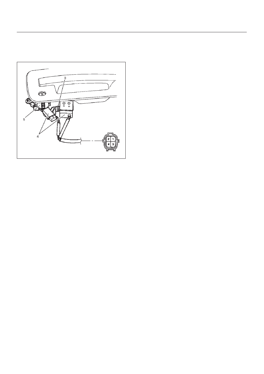
2. For the anti-theft system, be sure to install the push

rod(3) of key switch while pressing it to the door lock
cylinder(5) so that there is no continuity between the
key switch(4) side connector terminal No. D6–2 and
D6–4 (No. D16–2 and D16–4: passenger side).

632RS010

3. Tighten the outside handle and key switch fixing bolts

to the specified torque.

Torque: 9 N·m (0.9kg·m/78 lb in)

4. Check for smooth outside handle and lock cylinder

operation.

SECURITY AND LOCKS

8H–7

Rear Door Lock Assembly

Rear Door Lock Assembly and Associated Parts

652RW004

Legend

(1) Door Trim Panel

(2) Waterproof Sheet
(3) Door Lock Assembly

Removal

1. Disconnect the battery ground cable.
2. Remove the door trim panel.
3. Remove the waterproof sheet.

D

Refer to the Rear Window Regulator And Glass in
Body Structure section.

8H–8

SECURITY AND LOCKS

4. Disconnect the locking links (arrow marks positions)

and remove the fixing screws to remove the door lock
assembly.

652RS002

Legend

(1) Outside Handle
(2) To Inside Lock Knob
(3) To Inside Handle
(4) To Actuator

Installation

To install, follow the removal steps in the reverse order,
noting the following points.

1. Apply chassis grease to the lock assembly and striker

moving surface.

2. Tighten the door lock assembly fixing screws to the

specified torque.

Torque: 7 N·m (0.7kg·m/61 lb in)

3. Check that the door lock operates smoothly.

SECURITY AND LOCKS

8H–9

Rear Outside Handle

Rear Outside Handle and Associated Parts

652RW003

Legend

(1) Door Trim Panel

(2) Waterproof Sheet
(3) Outside Handle

Removal

1. Disconnect the battery ground cable.
2. Remove the door trim panel.
3. Remove the waterproof sheet.

D

Refer to the Rear Window Regulator And Glass in
Body Structure section.

4. Disconnect the locking link (arrow mark position) and

remove three fixing bolts to remove the outside
handle.

652RS003


Content   ..  1053  1054  1055  1056   ..