Content .. 1052 1053 1054 1055 ..
Isuzu Trooper (1998-2002 year). Manual - part 1054
8H–2
SECURITY AND LOCKS
Service Precaution
WARNING: IF SO EQUIPPED WITH A
SUPPLEMENTAL RESTRAINT SYSTEM (SRS),
REFER TO THE SRS COMPONENT AND WIRING
LOCATION VIEW IN ORDER TO DETERMINE
WHETHER YOU ARE PERFORMING SERVICE ON OR
NEAR THE SRS COMPONENTS OR THE SRS
WIRING. WHEN YOU ARE PERFORMING SERVICE
ON OR NEAR THE SRS COMPONENTS OR THE SRS
WIRING, REFER TO THE SRS SERVICE
INFORMATION. FAILURE TO FOLLOW WARNINGS
COULD RESULT IN POSSIBLE AIR BAG
DEPLOYMENT, PERSONAL INJURY, OR
OTHERWISE UNNEEDED SRS SYSTEM REPAIRS.
CAUTION: Always use the correct fastener in the
proper location. When you replace a fastener, use
ONLY the exact part number for that application.
ISUZU will call out those fasteners that require a
replacement after removal. ISUZU will also call out
the fasteners that require thread lockers or thread
sealant. UNLESS OTHERWISE SPECIFIED, do not
use supplemental coatings (Paints, greases, or other
corrosion inhibitors) on threaded fasteners or
fastener joint interfaces. Generally, such coatings
adversely affect the fastener torque and the joint
clamping force, and may damage the fastener. When
you install fasteners, use the correct tightening
sequence and specifications. Following these
instructions can help you avoid damage to parts and
systems.
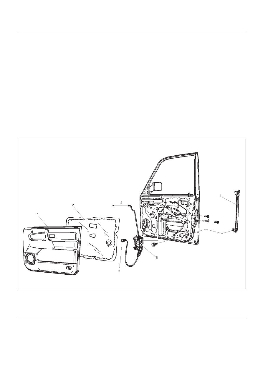
Front Door Lock Assembly
Front Door Lock Assembly and Associated Parts
632RS003
Legend
(1) Door Trim Panel
(2) Waterproof Sheet
(3) To Outside Handle
(4) Rear Guide Rail
(5) Door Lock Assembly
(6) Door Lock Switch Connector (W/Power Door
Lock)
Removal
1. Disconnect the battery ground cable.
2. Remove the door trim panel.
3. Remove the waterproof sheet.
Refer to the Front Window Regulator, Glass And
Glass Run in Body Structure section.