Isuzu Trooper (1998-2002 year). Manual - part 1030


  Index      Isuzu     Isuzu Trooper - service repair manual 1998-2002 year


Search            


Content   ..  1028  1029  1030  1031   ..


Isuzu Trooper (1998-2002 year). Manual - part 1030


8F–48

BODY STRUCTURE

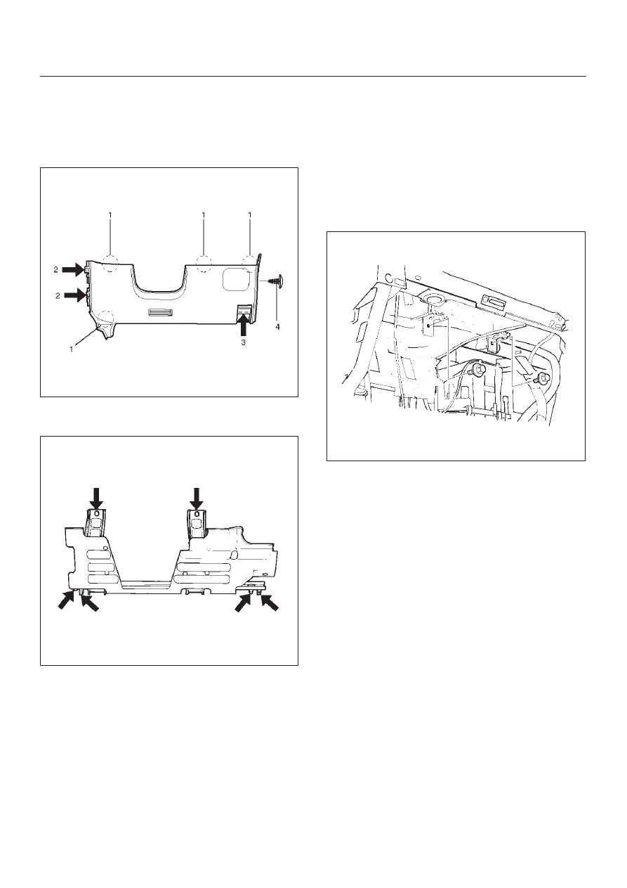
7. Remove instrument panel driver lower cover

assembly.

D

Remove the engine hood opener fixing screws.

D

Remove the 2 fixing screws (2), 1 fixing bolt (3), and
1 clip (4). Pull out the fasteners at the 4 positions
(1).

740RW105

8. Remove driver knee bolster assembly (W/SRS).

D

Remove the 6 fixing nuts.

740RW122

9. Remove front defroster grille.

D

Pry 8 claws on the front side toward you side (room
side) and raise the grille upward.

10. Remove instrument panel assembly.

D

Remove the 2 fixing bolts on the SRS adjust bracket
and the cross beam under the passenger inflator
module (W/SRS).

CAUTION: For precautions on installation or
removal of SRS — air bag system, refer to
Supplemental RestraintSystem (SRS) — AIR BAG in
Restraint section.

827RW031

D

Disconnect the 3 air conditioner control cables on
the unit side.

D

Remove the instrument harness connectors (5
connectors on the drivers side and 3 connectors on
the passenger side), the passenger inflator module
connector, the radio antenna cable plug, and the
ground cable fixing bolt on the center bracket.

D

Remove the 4 bolts (4) and the 2 nuts (3) under the
instrument panel assembly, and the upper left and
the upper right bolts (2) and the center nut (1).

8F–49

BODY STRUCTURE

740RW106

11. Remove passenger inflator module (W/SRS).

D

From the back of the instrument panel, remove the
4 fixing nuts (2) on the passenger inflator module (3)
and the 2 fixing nuts (1) and washers on the support
bracket (4), then disengage the 2 clips in order to
remove the passenger inflator module.

827RW032

12. Remove instrument panel cluster assembly.

D

Remove the 5 fixing screws (2) and pull the main
unit toward you and remove the clips at the 4
positions (1). Disconnect the switch connectors. 

740RW107

8F–50

BODY STRUCTURE

13. Remove meter assembly.

D

Remove the 4 meter assembly fixing screws and
disconnect the meter harness connectors. 

821RS034

14. Remove control lever assembly.

D

Refer to Control Lever Assembly And/Or Control
Cables in Heating And Ventilation section.

15. Remove radio assembly.

D

Remove 2 fixing screws.

16. Remove vent duct assembly.

D

Remove 5 fixing screws.

17. Remove instrument harness assembly.

D

Remove the 4 fixing screws, fasteners at the 4
positions and the clips at the 7 positions.

18. Remove side defroster grille.

NOTE: For the order of removal steps in which each
items contained in the instrument panel assembly are
removed individually, refer to the chart.

8F–51

BODY STRUCTURE

Installation

To install, follow the removal steps in the reverse order.
Order Of Removal/Installation Steps For Each Item

Removal Item

Removal Procedure

Removal Step

Front console
assembly

Shift knob (M/T), Power & Winter SW (A/T), Transfer knob, Seat
heater/Miller SW conn. and 4 screws

1, 2

Lower cluster
assembly

3 screws, Ciger lighter conn. and Ashtray illumination conn.

1

3

Glove box

2 screws

4

Instrument panel
passenger lower cover

7 screws and 1 clip

1

5

Passenger knee
bolster reinforcement

4 nuts and 4 bolts

1

6

Instrument panel driver
lower cover

Engine hood opening fixing screw, 2 screws, 1 bolt, 1 clip and
fasteners at 4 positions

1

3, 7

Driver knee bolster

6 nuts

1

3, 7, 8

Front defroster grille

Claws at 8 positions

9

Instrument panel
assembly

2 bolts (SRS adjust bracket

 cross beam), A/C control cable (Unit

side at 3 position), Instrument harness connector (Driver side 5
position, assist side 3 position), SRS module conn., Radio antenna
jack, Earth cable, 9 bolts and 3 nuts

1

10

Passenger inflator
module

4 nuts (SRS module

Instrument panel), 2 nuts 0 and 2 washers

(SRS module

support bracket) and 2 clips

1

6, 11

Instrument panel
cluster

5 Screws, fastener at 4 position and each SW conn.

1

3, 7, 12

Meter assembly

4 screws and connectors

1

3, 7, 12, 13

A/C control panel
assembly

4 screws and connectors

1

3, 7, 12, 14

Radio assembly

2 screws

1

3, 15

Vent duct assembly

5 screws

1

10, 16

Instrument harness
assembly

4 screws, fasteners at 4 position, and clips at 7 position

1

10, 17

Side defroster grille

18

M/T = Manual Transmission
A/T = Automatic Transmission
SRS = Supplemental Restraint System
A/C = Air Conditioning


Content   ..  1028  1029  1030  1031   ..