Isuzu Trooper (2000 year). Manual - part 64


  Index      Isuzu     Isuzu Trooper - service repair manual 2000 year


Search            


Content   ..  62  63  64  65   ..


Isuzu Trooper (2000 year). Manual - part 64


3C 21

FRONT SUSPENSION

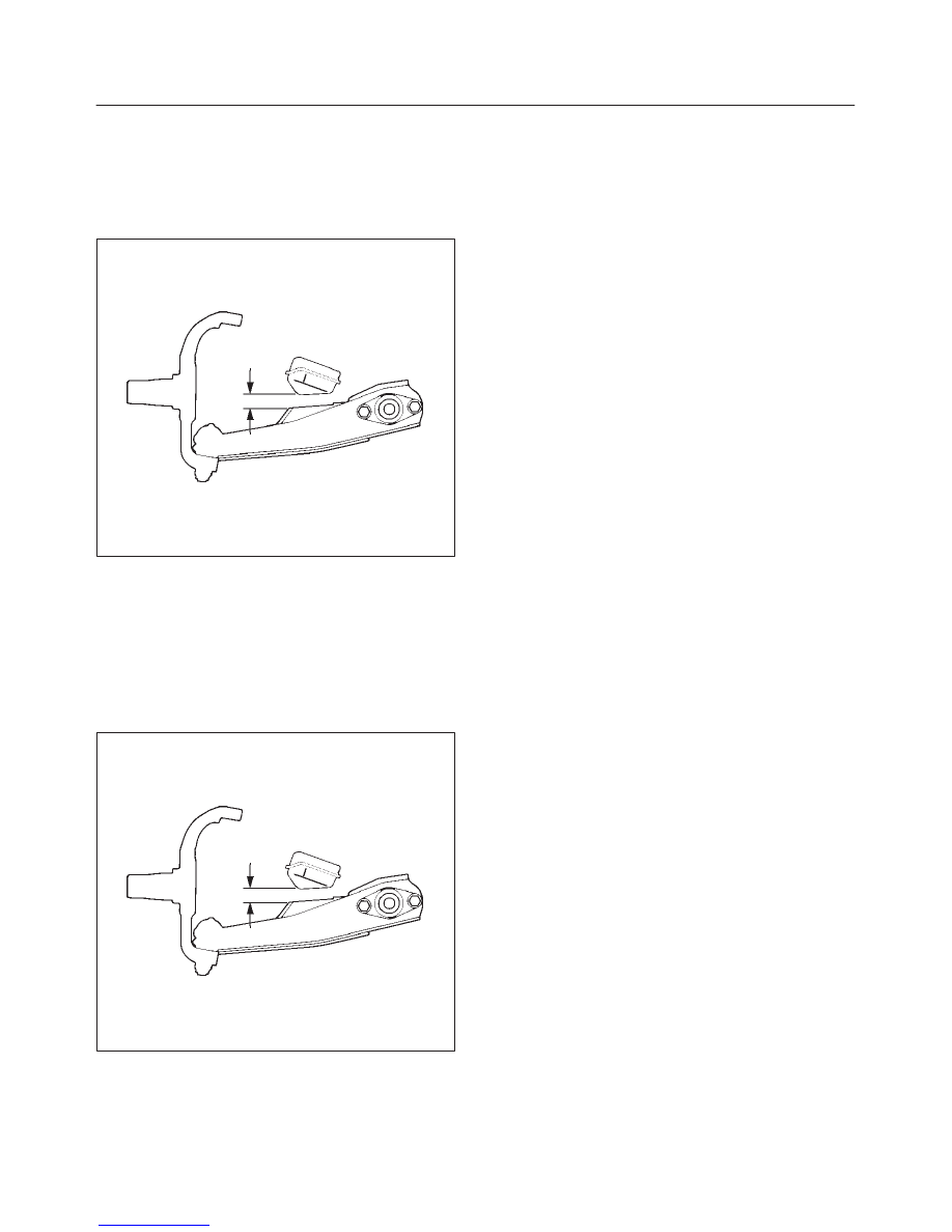
13. Install rear nut and washer and tighten lower link nut

finger–tight.

NOTE: Torque lower control arm nut after adjusting buffer
clearance.

Buffer clearance: 20 mm (0.79 in)
Torque: 196 N·m (145 lb ft)

450RS012

14. Install front nut and washer then tighten lower link nut

finger-tight.

NOTE: Torque lower control arm nut after adjusting buffer
clearance .

Buffer clearance: 20 mm (0.79 in)
Torque: 157 N·m (116 lb ft)

NOTE: Adjust the trim height. Refer to Front End
Alignment Inspection and Adjustment in Steering section.

450RS012

3C 22

FRONT SUSPENSION

Upper Ball Joint

Upper Ball Joint and Associated Parts

450RS022

Legend

(1) Bolt, Nut and Washer

(2) Upper Ball Joint 
(3) Nut and Cotter Pin

Removal

1. Raise the vehicle and support the frame with suitable

safety stands.

2. Remove the speed sensor from the knuckle. 

3C 23

FRONT SUSPENSION

3. Remove upper ball joint nut and cotter pin, then use

remover J–36831 to remove the upper ball joint from
the knuckle.

CAUTION: Be careful not to break the ball joint boot.

901RW043

4. Remove bolt and washer.
5. Remove upper ball joint.

Inspection and Repair

Make necessary parts replacement if wear, damage,
corrosion or any other abnormal conditions are found
through inspection.

D

Inspect the lower end boot for damage or grease leak.
Move the ball joint as shown in the figure to confirm its
normal movement.

D

Inspect screw/taper area of ball for damage.

D

If any defects are found by the above inspections,
replace the ball joint assembly with new one. 

450RS023

D

After moving the ball joint 4 or 5 times, attach nut then
measure the preload.

Starting torque: 0.5 –3.2 N·m (0.4–2.4 lb ft)

450RS024

If the above limits specified are exceeded, replace the ball
joint assembly.

Installation

1. Install upper ball joint.
2. Install bolt and nut, then tighten them to the specified

torque.

Torque: 57 N·m (42 lb ft)

3. Install nut and cotter pin, then tighten the nut to the

specified torque with just enough additional torque to
align cotter pin holes. Install new cotter pin.

Torque: 98 N·m (72 lb ft)

3C 24

FRONT SUSPENSION

Lower Ball Joint

Lower Ball Joint and Associated Parts

450RS025

Legend

(1) Bolt
(2) Lower Ball Joint

(3) Nut
(4) Nut and Cotter Pin

Removal

1. Raise the vehicle and support the frame with suitable

safety stands.

2. Remove wheel and tire assembly. Refer to Wheel

Replacement in this section.

3. Remove the outer track rod from the knuckle. Refer to

Steering Linkage in Steering section. 

4. Remove the retaining ring from the front axle driving

shaft to release the shaft from hub. Refer to Front Hub
and Disc in Driveline/Axle section.

5. Support lower control arm with a jack. 
6. Remove lower ball joint nut and cotter pin, then use

remover J–29107 to remove the lower ball joint from
the knuckle.

CAUTION: Be careful not to damage the ball joint
boot.

901RW042


Content   ..  62  63  64  65   ..