Isuzu KB P190. Manual - part 720
 

  Index      Isuzu     Isuzu KB P190 - service repair manual 2007 year


Search            


Content   ..  718  719  720  721   ..


Isuzu KB P190. Manual - part 720


Engine Mechanical – V6 

Page 6A1–103 


Page 6A1–103 

3.14  Crankshaft Front Seal 

Replace 

1 

Remove the crankshaft balancer assembly, refer to 

3.13  Crankshaft Balancer Assembly

. 

2 

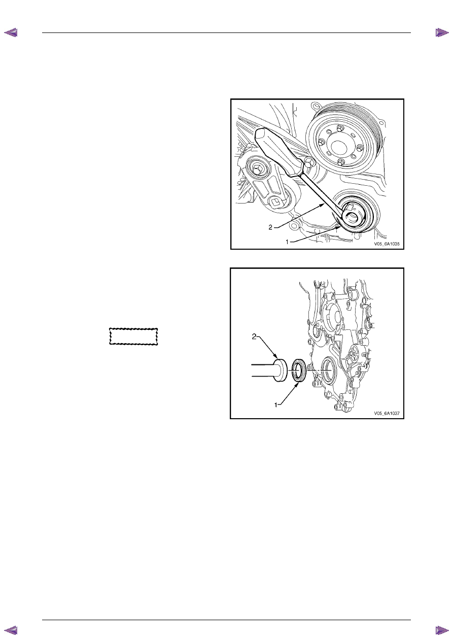
Using a flat bladed tool (2) or seal remover, Tool No. 
E-308, carefully remove the crankshaft front seal (1) 
from the front cover. 


Figure 6A1 – 81 

3 

Using crankshaft front seal installer, Tool No. J-29184 
(2) and a suitable hammer, install a new crankshaft 
front seal (1) until fully seated against the front cover 
housing. 

4 

Install the crankshaft balancer assembly, refer to  

3.13  Crankshaft Balancer Assembly

. 

CAUTION


Do not lubricate the crankshaft front oil seal 
or crankshaft balancer sealing surfaces. The 
crankshaft balancer is installed into a dry 
seal. 


Figure 6A1 – 82 

Engine Mechanical – V6 

Page 6A1–104 


Page 6A1–104 

3.15  Front Cover Assembly 

Remove 

1 

Drain the engine coolant, refer to 

Section 6B1 Engine Cooling

. 

2 

Remove the water outlet pipe and coolant pump assembly, refer to 

Section 6B1 Engine Cooling

: 

3 

Remove the camshaft covers, refer to 

3.12  Camshaft Cover

. 

4 

Remove the crankshaft balancer assembly, refer to 

3.13  Crankshaft Balancer Assembly

. 

5 

Disconnect the purge vent hose from the water outlet pipe. 

N O T E  

Do not disconnect the power steering pipes or 
drain the power steering fluid. 

6 

Remove the power steering pump reservoir mounting bracket, refer to 

3.8  Power Steering Pump Bracket

. 

7 

Remove the camshaft position sensor, refer to 

Section 6C1-3 Engine Management – V6 – Service Operations

. 

N O T E  

Do not disconnect the A/C compressor pipes. 


8 

Remove the bolt (2), 22 places, attaching the front 
cover assembly (1). 


CAUTION


Only use the prise points and a bolt in the 
jackscrew hole to remove the engine front 
cover.  


9 

Loosely install a 10 x 1.5 mm bolt in the jackscrew 
hole (1). 


10 

Using the prise points (2) located at the edge of the 
front cover and the jackscrew, shear the RTV sealant.

Figure 6A1 – 83 


Figure 6A1 – 84 

Engine Mechanical – V6 

Page 6A1–105 


Page 6A1–105 

11 

Remove the front cover assembly (1). 


Figure 6A1 – 85 

Disassemble 

1 

Remove the crankshaft front oil seal (1) from the 
engine front cover (2) using a flat bladed tool or seal 
remover, Tool No. E-308. Discard the seal. 


Figure 6A1 – 86 

2 

Remove the camshaft position actuator valve oil 
seals (1) from the engine front cover (2). Discard the 
seals. 


Figure 6A1 – 87 

Engine Mechanical – V6 

Page 6A1–106 


Page 6A1–106 

3 

Remove the coolant pump seal (1) from the engine 
front cover (2). Discard the seal. 


Figure 6A1 – 88 

Clean 

4 

Remove any RTV sealant (1) from the engine front 
cover using a plastic or wood scraper. 

CAUTION


•  Insert a piece of cardboard between the 

front of the oil pan and oil pump to 
prevent any contaminants from falling 
into the oil pan. 

•  Do not use a sharp or metal gasket 

scraper to clean the sealing surfaces. 

5 

Clean out any debris from the bolt holes. 

6 

Clean the front cover with a suitable cleaning solvent.

7 

Dry the front cover with compressed air. 


Safety glasses must be worn when using 
compressed air. 


Figure 6A1 – 89 

8 

Use compressed air to remove any engine coolant from the engine cooling passages and from the top of the oil 
pan oil deflector. 


Content   ..  718  719  720  721   ..